Decorative laminate with non-visible light activated material and system and method for using the same

a technology of non-visible light activated materials and decorative laminates, which is applied in the field of decorative laminates and systems, can solve the problems of reducing manufacturing efficiency, difficulty in later inspections to determine whether a decorative laminate has been applied correctly, and wasting decorative laminate scraps

Active Publication Date: 2017-08-01
THE BOEING CO
View PDF8 Cites 80 Cited by
  • Summary
  • Abstract
  • Description
  • Claims
  • Application Information

AI Technical Summary

Benefits of technology

[0012]Example implementations of the present disclosure provide an improved decorative laminate and system and method for using the same that provide advantages over known decorative laminates, systems, and method. As discussed in the below detailed description, embodiments of the improved decorative laminate and system and method of using the same may provide significant advantages over existing decorative laminates, and systems and methods of using the same.

Problems solved by technology

Such removal of the positional reference markings or labels may result in difficulty with later inspections to determine whether a decorative laminate has been applied correctly.
In addition, if decorative laminates are not aligned properly on the composite panels, such misalignment may not be discovered until final assembly and may result in having to discard the misaligned decorative laminates as scrap.
This may, in turn, result in decreased manufacturing efficiency and increased manufacturing time and costs.
However, it may be difficult to later locate and identify such non-decorative information or markings without disassembling or removing the finished composite panel product in some way to access the information.
This may, in turn, result in increased time, labor and costs for maintenance and repair of such finished composite panel products.
However, known decorative laminate systems and methods may not provide for multiple interior designs or branding features within the same space or area that may each be selectively visible or non-visible.

Method used


Image

  • Decorative laminate with non-visible light activated material and system and method for using the same
  • Decorative laminate with non-visible light activated material and system and method for using the same
  • Decorative laminate with non-visible light activated material and system and method for using the same

Examples


Embodiment Construction

[0042]Disclosed embodiments will now be described more fully hereinafter with reference to the accompanying drawings, in which some, but not all of the disclosed embodiments are shown. Indeed, several different embodiments may be provided and should not be construed as limited to the embodiments set forth herein. Rather, these embodiments are provided so that this disclosure will be thorough and will fully convey the scope of the disclosure to those skilled in the art.

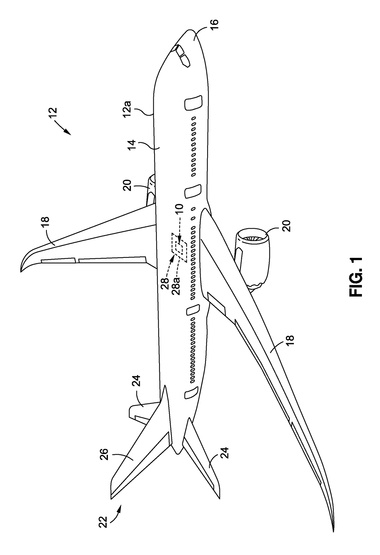
[0043]Now referring to the Figures, FIG. 1 is an illustration of a perspective view of an air vehicle 12, such as in the form of aircraft 12a, that incorporates one or more embodiments of a decorative laminate 10, of the disclosure. As further shown in FIG. 1, the air vehicle 12, such as in the form of aircraft 12a, comprises a fuselage 14, a nose 16, wings 18, engines 20, and an empennage 22 comprising horizontal stabilizers 24 and a vertical stabilizer 26.

[0044]As further shown in FIG. 1, the air vehicle 12, such as ...


PUM

PropertyMeasurementUnit
thicknessesaaaaaaaaaa
thicknessaaaaaaaaaa
thicknessaaaaaaaaaa

Abstract

There is provided a decorative laminate having a first laminate layer, a second laminate layer, and a decorative layer disposed selectively between the first laminate layer and the second laminate layer. The decorative layer includes one or more visible materials, and one or more non-visible light activated materials that change from a non-visible state to a visible state when exposed to a light source. The light source includes an ultraviolet (UV) light source or an infrared (IR) light source. The decorative laminate further has a resin layer disposed on the second laminate layer. The first laminate layer, the decorative layer, the second laminate layer, and the resin layer are laminated together to form the decorative laminate configured for application to a structural component.

Description

BACKGROUND[0001]1) Field of the Disclosure[0002]The disclosure relates generally to decorative laminates and systems and methods of using the same, and more particularly, to decorative laminates having non-visible light activated material and systems and methods of using the same, where the decorative laminates are used on structural components, such as aircraft interior structural components.[0003]2) Description of Related Art[0004]Decorative laminates are used in a wide variety of applications, including for surfaces of walls, countertops, and other structures, such as interior structural components of aircraft. For example, decorative laminates may be applied to the surfaces of such aircraft interior structural components as cabin interior sidewall and ceiling panels, floor panels, stowage bins, lavatory and galley panels and structures, bulkhead partitions, window shades, and other aircraft interior structural components.[0005]Decorative laminates typically include a base or sub...

Claims


Application Information

Patent Timeline
Patent Type & Authority Patents(United States)
IPC IPC(8): B32B3/10B32B15/082B32B15/20B32B27/30B32B27/08B44F1/10B32B7/12
CPCB44F1/10B32B3/10B32B7/12B32B15/082B32B15/20B32B27/08B32B27/304B32B2255/10B32B2451/00B32B2605/18B44C5/04B32B27/20B32B2307/4026B32B2307/748B32B27/36B32B27/38B32B2307/40B32B3/00B32B27/42B32B2307/4023B32B27/40B32B2250/44B32B7/06
Inventor YOUNG, STEPHEN M.DAVISON, CARL A.
Owner THE BOEING CO
Why Eureka
Try Eureka