Method and arrangement for controlling an internal combustion engine, comprising at least two control units

a control unit and internal combustion engine technology, applied in the direction of electric control, fuel injection control, machines/engines, etc., can solve the problems of no longer receiving or correctly receiving, no longer generating a defined pulse-width-modulated signal, and no longer being able to properly time the pulse-width-modulated signal, etc., to achieve the effect of convenient installation

Active Publication Date: 2017-08-01
ROLLS ROYCE SOLUTIONS GMBH
View PDF37 Cites 0 Cited by
  • Summary
  • Abstract
  • Description
  • Claims
  • Application Information

AI Technical Summary

Benefits of technology

[0007]The invention is based on the goal of creating a method and an arrangement for controlling an internal combustion engine, wherein in particular the failure safety is increased and a seamless switchover to a redundant control system in the event of a malfunction is possible without the need for a complicated checking procedure. The invention is also based on the goal of creating a switchover device for use in the control of an internal combustion engine and an internal combustion engine, wherein in particular the problems cited above are solved and / or the advantages cited above are realized.
[0008]The goal is achieved by a method in which. This method is characterized in that a switchover device is provided. For the actuation of at least one function of the internal combustion engine, this device passes along the at least one control signal of the first engine control unit to the engine. The first engine control unit, therefore, transmits its control signal not directly to the internal combustion engine but rather by way of the switchover device. The first engine control unit sends a sign-of-life signal to the switchover device, which indicates the functionality of the first engine control unit. It is provided that the sign-of-life signal is sent by the first engine control unit continuously or periodically, i.e., uninterruptedly or at intervals, to the switchover device. If an error or a malfunction occurs, wherein the proper actuation of the at least one function of the internal combustion engine by the first engine control unit is put at risk, the first engine control unit does not transmit the sign-of-life signal or does not transmit it correctly to the switchover device, so that it is no longer received or no longer correctly received by it. The first engine control unit preferably stops transmitting the sign-of-life signal. In this case, the switchover device stops passing along the control signal of the first engine control unit to the internal combustion engine, and it begins passing along the control signal generated by the second engine control unit to the internal combustion engine for actuation of the at least one function of the engine. The switchover device therefore switches the control of the internal combustion engine from the first engine control unit to the second engine control unit in the event of a malfunction, wherein this can proceed seamlessly. Because, in the event of a malfunction, the first engine control unit does not send an error signal but rather stops sending the sign-of-life signal or stops sending it correctly, wherein it preferably stops sending the sign-of-life signal, even the complete failure of the first engine control unit in particular is noticed by the switchover device, so that a seamless switchover to the second engine control unit is possible. There is no need for a two-stage check, because the second engine control unit does not actively have to check for the failure of the first engine control unit if no data are being transmitted; on the contrary, the switchover device reacts immediately to the absence or incorrect reception of the sign-of-life signal of the first engine control unit by switching over to the second engine control unit, without any further measures being taken. The method is therefore very simple and reliable.

Problems solved by technology

If an error or a malfunction occurs, wherein the proper actuation of the at least one function of the internal combustion engine by the first engine control unit is put at risk, the first engine control unit does not transmit the sign-of-life signal or does not transmit it correctly to the switchover device, so that it is no longer received or no longer correctly received by it.
A solution of this type is usually believed to be disadvantageous, because it is difficult or nearly impossible to generate a defined pulse-width-modulated signal on the basis of a program.
In the method under discussion here, however, this weakness is effectively utilized, in that the pulse-width-modulated signal is detected in the switchover device by suitable hardware and checked for deviations in its timing.
If the software of the first engine control unit is malfunctioning, it is no longer able to time the pulse-width-modulated signal properly.

Method used


Image

  • Method and arrangement for controlling an internal combustion engine, comprising at least two control units
  • Method and arrangement for controlling an internal combustion engine, comprising at least two control units
  • Method and arrangement for controlling an internal combustion engine, comprising at least two control units

Examples


Embodiment Construction

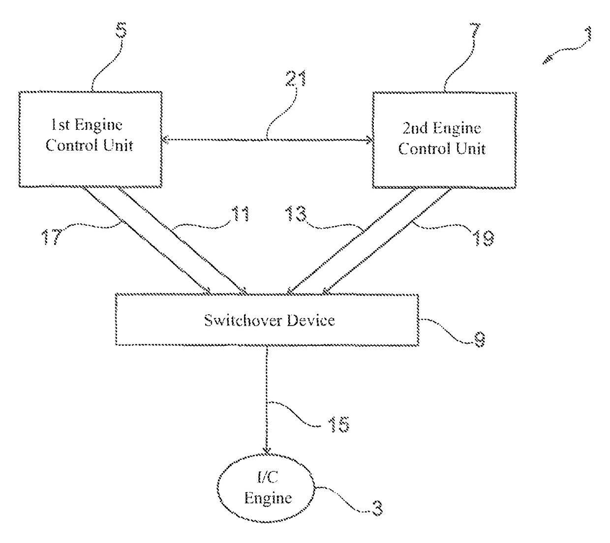
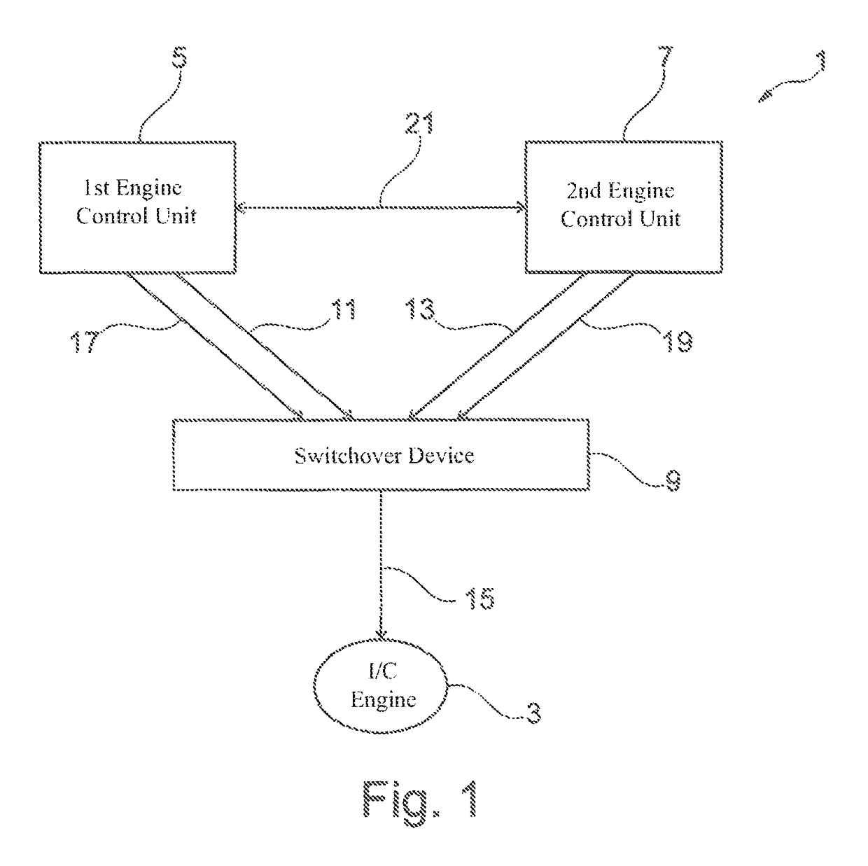
[0058]FIG. 1 shows a schematic diagram of an exemplary embodiment of an arrangement 1 for controlling an internal combustion engine 3. The arrangement 1 comprises a first engine control unit 5, a second engine control unit 7, and a switchover device 9.

[0059]The first engine control unit 5 and the second engine control unit 7 are able to generate control signals, which serve to actuate at least one function of the internal combustion engine, preferably to control and / or to automatically control a plurality of functions or the entire internal combustion engine. The first engine control unit 5 is functionally connected by a functional connection 11 to the switchover device 9, the second engine control unit 7 being connected to it by a functional connection 13, these connections allowing the control signals from each control unit to be transmitted to the switchover device. The switchover device 9 is functionally connected to the internal combustion engine 3 by a third functional connect...


PUM


Abstract

A method for controlling an internal combustion engine, wherein a first engine control device generates a control signal to actuate a function of the engine. A switchover device transmits the control signal of the first control device to the engine to actuate the function of the engine. The first control device transmits a sign-of-life signal which indicates functionality of the control device to the switchover device. The first engine control device does not transmit the sign-of-life signal or transmits the signal incorrectly if a fault occurs which endangers proper actuation of the function of the engine by the first engine control device. If the sign-of-life signal of the first engine control device is not or is incorrectly received by the switchover device, the switchover device stops transmitting the control signals of the first engine control device and starts transmitting a control signal generated by a second engine control device to the engine to actuate the function of the engine.

Description

[0001]The present application is a 371 of International application PCT / EP2014 / 000254, filed Jan. 30, 2014, which claims priority of DE 10 2013 201 702.2, filed Feb. 1, 2013, the priority of these applications is hereby claimed and these applications are incorporated herein by reference.BACKGROUND OF THE INVENTION[0002]The invention pertains to a method for controlling an internal combustion engine, to a switchover device for use in controlling an internal combustion engine, to an arrangement for controlling an internal combustion engine, and to an internal combustion engine.[0003]Methods and arrangements of the type considered here are known. An engine control unit is provided, which generates at least one control signal to actuate at least one function of the internal combustion engine, typically many or even all of the functions of the internal combustion engine. If, however, a malfunction occurs in the engine control unit, in the sensors functionally connected to the engine cont...

Claims


Application Information

Patent Timeline
Patent Type & Authority Patents(United States)
IPC IPC(8): F02D41/22F02D41/20F02D41/26F02D41/38F02D11/10
CPCF02D41/26F02D41/22F02D41/266F02D41/3809F02D11/107F02D2041/2058F02D2041/227F02D2400/08
Inventor MEHR, ANDREASHIRSCHLE, CHRISTOPHHENKER, JANELZE, ROGER
Owner ROLLS ROYCE SOLUTIONS GMBH
Why Eureka
Try Eureka