Test module with blocks of universal and specific resources

a technology of test modules and blocks, applied in the direction of electronic circuit testing, measurement devices, instruments, etc., can solve the problems of significant development costs, cost saving, and reducing programming time and therefore test time, so as to improve the failure safety of the system

Active Publication Date: 2013-02-26
ADVANTEST CORP
View PDF8 Cites 0 Cited by
  • Summary
  • Abstract
  • Description
  • Claims
  • Application Information

AI Technical Summary

Benefits of technology

[0012]By providing such a common “universal channel” component in all channels of a test system, a defined interface may be provided for coupling to a workstation or any other central control instance to a channel specific driver / receiver which may, in turn, be coupled to the device under test (DUT). Such an interface may be provided with respect to a mechanical, an electrical, a volume and / or a software coupling. Consequently, exemplary embodiments may reduce the effort for developing new test modules, may shorten development times, may reduce the development costs, may reduce the costs per module because of higher numbers of components (particularly of universal sections), and may reduce production costs due to a smaller number of variants.
[0017]By providing the standard portion in all types of test modules, even very simple modules (like a power supply module or a DC module) may then have, with very few additional costs due to the standardized configuration of this universal portion, additional components like a sequence control steering for a test procedure. This may allow to improve the functionality of such low function test modules, like power supply or DC.
[0022]A further advantage of exemplary embodiments may be that (in contrast to conventional approaches in which the test setup has to be programmed completely sequentially and separately for each block or test module one after the other) it is possible to program at least a part of the information into the standardized portion for a plurality of test modules together, due to the separation between a standardized component and an individualized component. Thus, only the small additional individualized portions have to be programmed individually for each of the test modules, but a main general programming portion may be performed centrally. This may reduce programming time and therefore test time, saving costs.
[0024]It is also possible to synchronize the test execution for different modules or boards to one another. This allows for a synchronous execution of actions by the individual test modules, simplifying the system. For example, a chronology of the execution of individual test sequences may be synchronized with a central programming. Therefore, according to an exemplary embodiment, a parallel programming of the standard portion of the test modules may be performed allowing a refinement of the interactions of the modules contributing to the test routine.
[0026]Embodiments of the invention may have the advantage that a faster test is possible. Furthermore, a synchronous execution of the measurement is possible. The development efforts for developing a new test module may be reduced, since all unspecific general resources and capabilities may be bundled in a universal section which may be developed once for a plurality of different test modules.
[0045]The at least partial configuration of at least two of the universal sections of the plurality of test modules simultaneously may comprise synchronizing the performance of at least two of the plurality of test modules. When, for instance a timing, or other operation parameters of the universal sections are configured together, this may allow to synchronize the complete workflow of the test. By synchronizing the individual units, the failure safety of the system may be improved.

Problems solved by technology

This may involve significant development costs.
This may reduce programming time and therefore test time, saving costs.

Method used


Image

  • Test module with blocks of universal and specific resources
  • Test module with blocks of universal and specific resources
  • Test module with blocks of universal and specific resources

Examples


Embodiment Construction

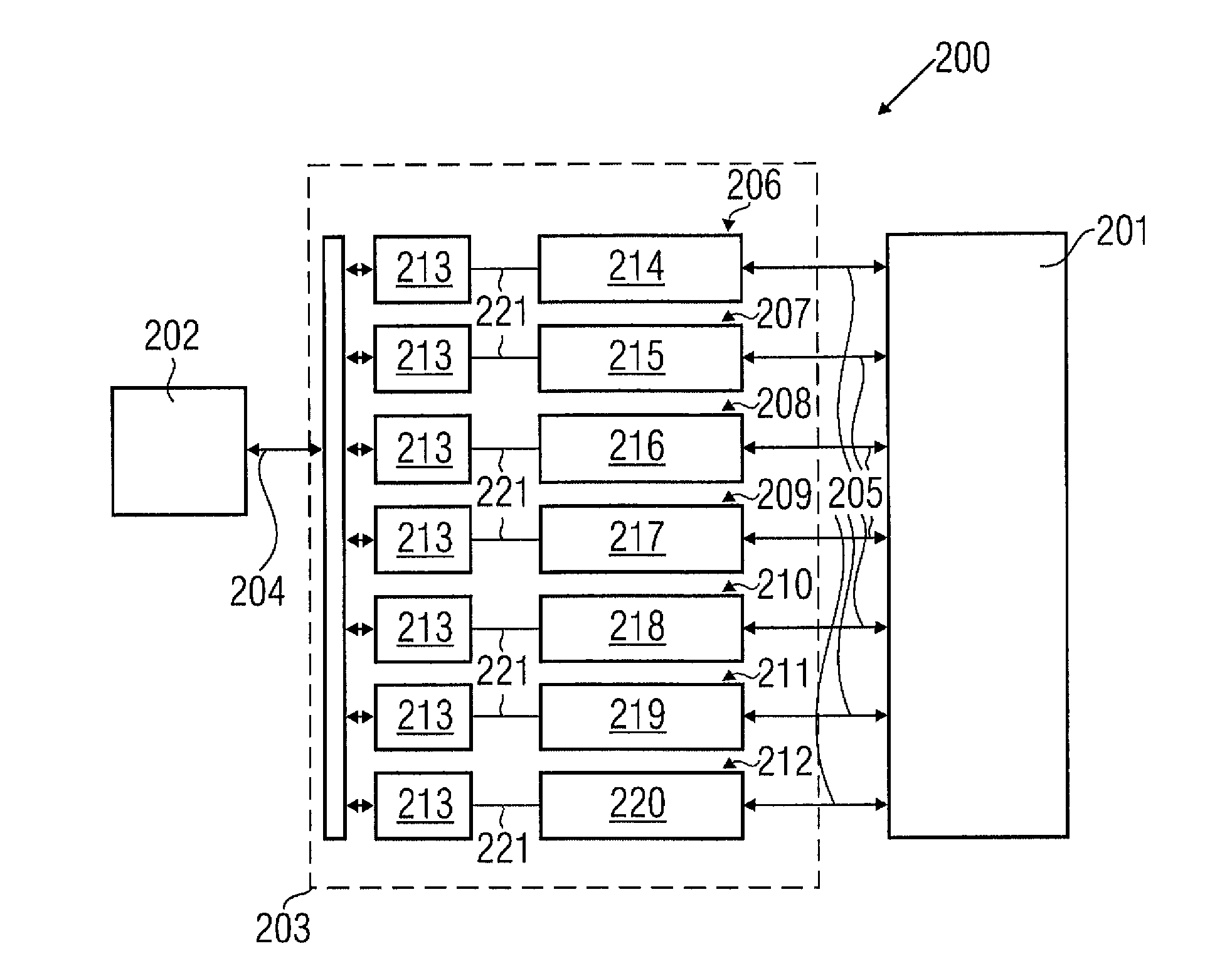
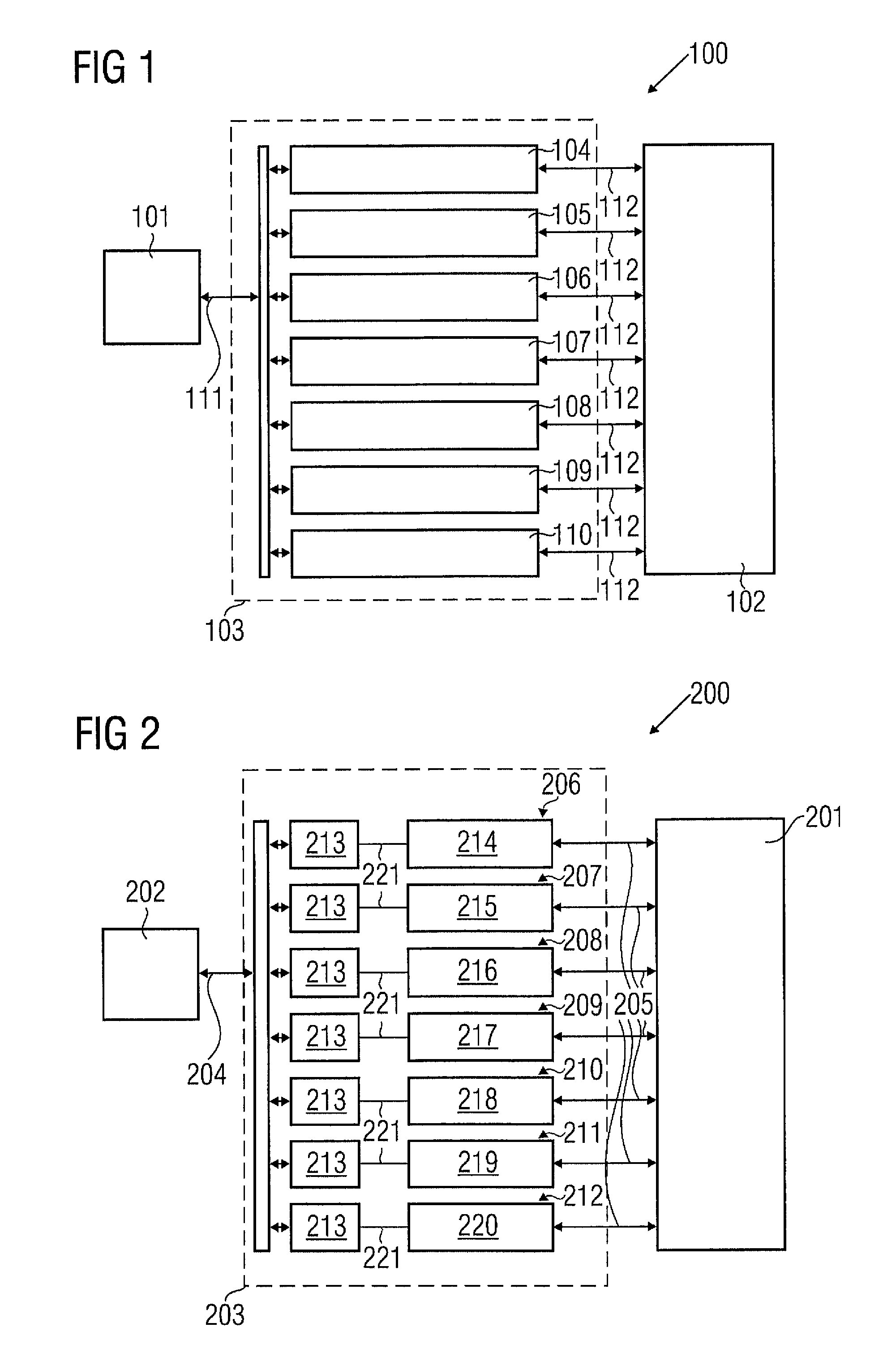
[0051]In the following, referring to FIG. 1, a test apparatus 100 will be explained.

[0052]The test apparatus 100 comprises a workstation 101 as a central control device for the System 100. Furthermore, a device under test 102, for instance a storage product to be tested, is provided in the System 100. An actual test device 103 is connected between the workstation 101 and the device under test 102. It comprises a plurality of test modules 104 to 110. The test modules 104 to 108 are digital channel test modules adapted to generate a digital test signal to be applied to pins of the device under test 102. The test module 109 is an analog channel module adapted to apply an analog waveform to pins of the DUT 102. The test module 110 is a power supply channel adapted to generate a power supply signal for powering the DUT 102 during the test.

[0053]The measurement head 103 comprises a first interface 111 interfacing between the workstation 101 and the test device 103. A further interface 112...


PUM


Abstract

A test module for a test apparatus for testing a device under test, the test module being adapted for performing a specific test function and having a universal section adapted to provide test resources being unspecific with regard to the test function of the test module, the universal section having a control interface adapted to be connected to a central control device of the test apparatus, and having a specific section to be coupled to the universal section and adapted to provide test resources being specific with regard to the test function of the test module, the specific section having a device under test interface adapted to be connected to the device under test.

Description

[0001]The present invention relates to tests of devices under test using a test device. This application is a 371 of PCT / EP2006 / 065080 filed on Aug. 4, 2006.BACKGROUND OF THE INVENTION[0002]For testing electronic devices, in particular integrated electronic circuits providing electrical input and output signals (for instance digital inputs or outputs, analog inputs or outputs, RF inputs or outputs, static / DC inputs or outputs), a test or stimulus signal is fed to an input of the device under test, and a response signal of the device under test is evaluated by an automatic test equipment, for example by comparison with expected data. Such an automatic test equipment has included a particular test functionality, that it to say test functions or routines which the test equipment may carry out. This test functionality may be incorporated in the test equipment in the form of executable software code.[0003]An example for an available test device is the 93000 test device of Agilent Technol...

Claims


Application Information

Patent Timeline
Patent Type & Authority Patents(United States)
IPC IPC(8): G01R31/02
CPCG01R31/31907G01R31/3183G01R31/319
Inventor WEYH, ANDREENEUWEILER, ROLF
Owner ADVANTEST CORP
Why Eureka
Try Eureka