
Orthogonal acceleration coaxial cylinder time of flight mass analyser

a mass analyser and coaxial cylinder technology, applied in mass spectrometers, instruments, particle separator tubes, etc., can solve the problems of severe mass range limitation, ion transmission, and performance at a cost to sensitivity (ion transmission), so as to increase the entrance energy and consequentially reduce the amount of upstream components

Active Publication Date: 2017-08-01
MICROMASS UK LTD
View PDF22 Cites 10 Cited by
  • Summary
  • Abstract
  • Description
  • Claims
  • Application Information

AI Technical Summary

Benefits of technology

This approach results in higher resolution and transmission, enabling longer flight paths without beam divergence losses and allowing for multipass configurations with improved sensitivity and mass range coverage.

Problems solved by technology

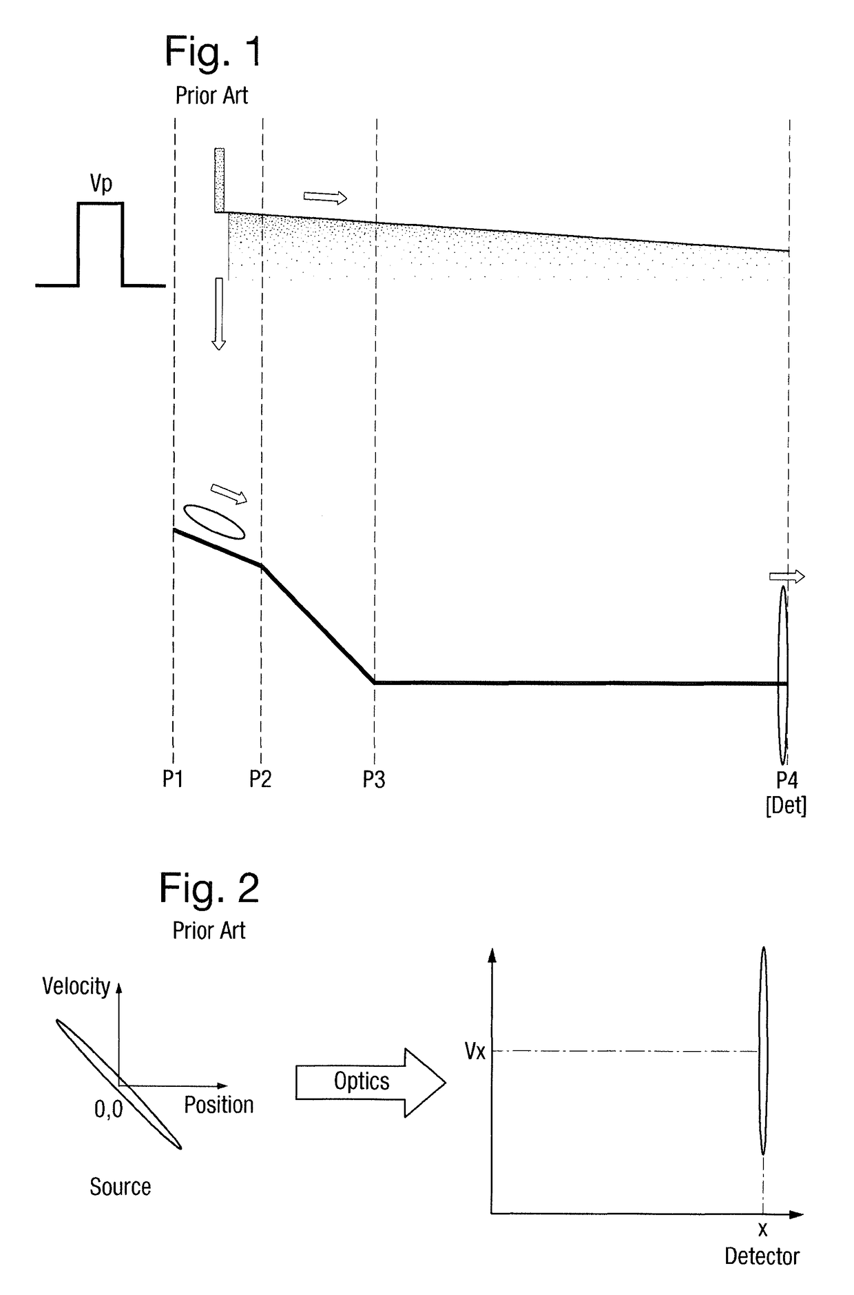
So as the beam traverses the spectrometer it gets weaker due to these losses and also defocusing (divergence) of the ion beam due to its initial velocity spread.
Resolutions as high as 50,000 to 100,000 are achievable with such a geometry but this performance comes at a cost to sensitivity (ion transmission).
As a result, some ions will follow helical trajectories which would miss the extraction port and hence not be detected by the ion detector.
The modified Spiratron arrangement disclosed in WO 2005 / 040785 would therefore also have a severe mass range limitation.

Method used


Image

  • Orthogonal acceleration coaxial cylinder time of flight mass analyser
  • Orthogonal acceleration coaxial cylinder time of flight mass analyser
  • Orthogonal acceleration coaxial cylinder time of flight mass analyser

Examples


Embodiment Construction

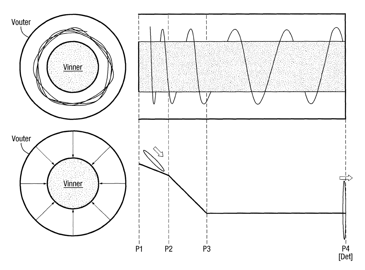
[0194]A preferred embodiment of the present invention will now be described with reference to FIG. 5. FIG. 5 shows a preferred embodiment of the present invention wherein a Time of Flight mass analyser is provided comprising two coaxial cylindrical electrodes with an annular ion guiding volume therebetween.

[0195]According to the preferred embodiment ions are confined radially between two coaxial cylinders held at different potentials Vouter and Vinner. The ion beam (which is preferably a packet of ions containing the different mass to charge ratio species to be analysed) approaches the outer cylinder where either a hole or a gap through which the ion beam may pass is preferably provided.

[0196]Ions entering the annular ion guiding volume preferably form stable circular orbits by increasing the field between inner and outer cylinders as the beam is entering the device. In the absence of any other fields once inside the cylinders the ions preferably remain in orbit but will disperse in...


PUM


Abstract

A Time of Flight mass analyzer is disclosed comprising an annular ion guide having a longitudinal axis and comprising a first annular ion guide section and a second annular ion guide section. Ions are introduced into the first annular ion guide section so that the ions form substantially stable circular orbits within the first annular ion guide section about the longitudinal axis. The ions are then orthogonally accelerated ions from the first annular ion guide section into the second annular ion guide section. An ion detector is disposed within the annular ion guide and has an ion detecting surface arranged in a plane which is substantially perpendicular to the longitudinal axis.

Description

CROSS-REFERENCE TO RELATED APPLICATION[0001]This application is the National Stage of International Application No. PCT / GB2013 / 051271, filed 16 May 2013, which claims priority from and the benefit of US Provisional Patent Application Ser. No. 61 / 650,008 filed on 22 May 2012, European Patent Application No. 12168612.5 filed on 21 May 2012, United Kingdom Patent Application No. 1208847.2 filed on 18 May 2012, United Kingdom Patent Application No. 1216489.3 filed on 14 Sep. 2012, United Kingdom Patent Application No. 1216488.5 filed on 14 Sep. 2012 and United Kingdom Patent Application No. 1216486.9 filed on 14 Sep. 2012. The entire contents of these applications are incorporated herein by reference.BACKGROUND OF THE PRESENT INVENTION[0002]The present invention relates to a Time of Flight mass analyser, a mass spectrometer, a method of mass analysing ions and a method of mass spectrometry.[0003]Reference is made to W. C. Wiley, I. H. McLaren, “Time-of-Flight Mass Spectrometer with Impr...

Claims


Application Information

Patent Timeline
Patent Type & Authority Patents(United States)
IPC IPC(8): H01J49/40H01J49/00
CPCH01J49/401H01J49/405H01J49/406H01J49/408H01J49/0031G01N2223/506
Inventor HOYES, JOHN BRIANLANGRIDGE, DAVID J.WILDGOOSE, JASON LEE
Owner MICROMASS UK LTD
Learn More