Frictional vibration damper

a damper and friction technology, applied in the direction of springs/dampers, textiles and papermaking, other washing machines, etc., can solve the problems of high cost and manufacturing difficulties, and achieve the effect of enhancing the integrity and rigidity of the damper, facilitating the manufacturing process, and simple and cheap design

Active Publication Date: 2017-08-15
AKSISTEM ELEKTROMEKANIK SANAYI & TICARET LTD STI
View PDF8 Cites 0 Cited by
  • Summary
  • Abstract
  • Description
  • Claims
  • Application Information

AI Technical Summary

Benefits of technology

[0006]Primary object of the present invention is to provide a frictional damper having a piston rod manufactured by rolling a sheet material, thereby providing a simple and cheap design facilitating manufacturing process.
[0007]Another object of the present invention is to provide a frictional damper having a piston rod manufactured by rolling a sheet material, said sheet material forming a tubular body supported by a carrier piece thereby enhancing integrity and rigidity of said damper.
[0008]Another object of the present invention is to provide a frictional damper whose piston rod is in the form of a tubular body, said tubular body having connection elements along its side edges in the longitudinal direction for maintaining rigidity and integrity of the piston rod during operation of the damper.
[0009]Still another object of the present invention is to provide frictional damper having a wavy profile at one end of its piston rod, said wavy profile entrapping lubricant material in order to enhance effective service life of said damper and provide a less noisy operation.

Problems solved by technology

Using two steel semi cylinders and a coupling ring for attaching the same to each other leads to manufacturing difficulties and high costs.

Method used


Image

  • Frictional vibration damper
  • Frictional vibration damper
  • Frictional vibration damper

Examples


Embodiment Construction

[0029]The following numerals are intended for a better understanding of the drawing whose brief descriptions are provided above.

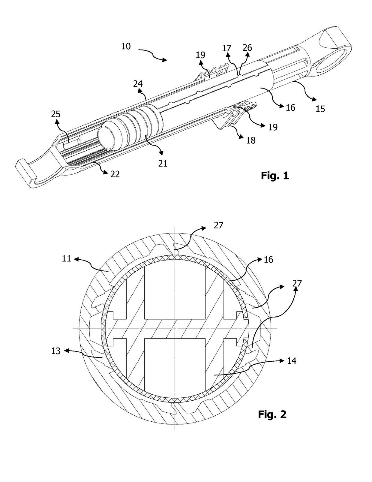
[0030]10. Frictional vibration damper

[0031]11. Profile of the piston body

[0032]12. Cap

[0033]13. Cavity

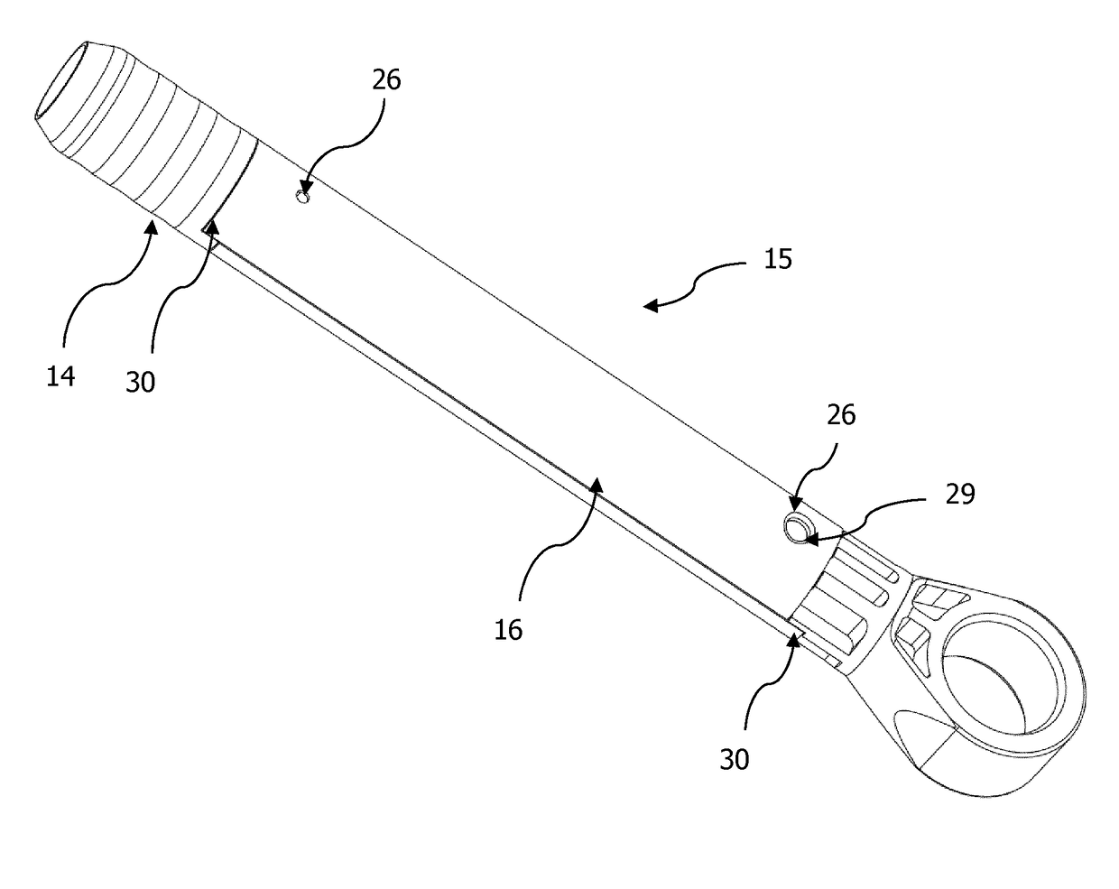
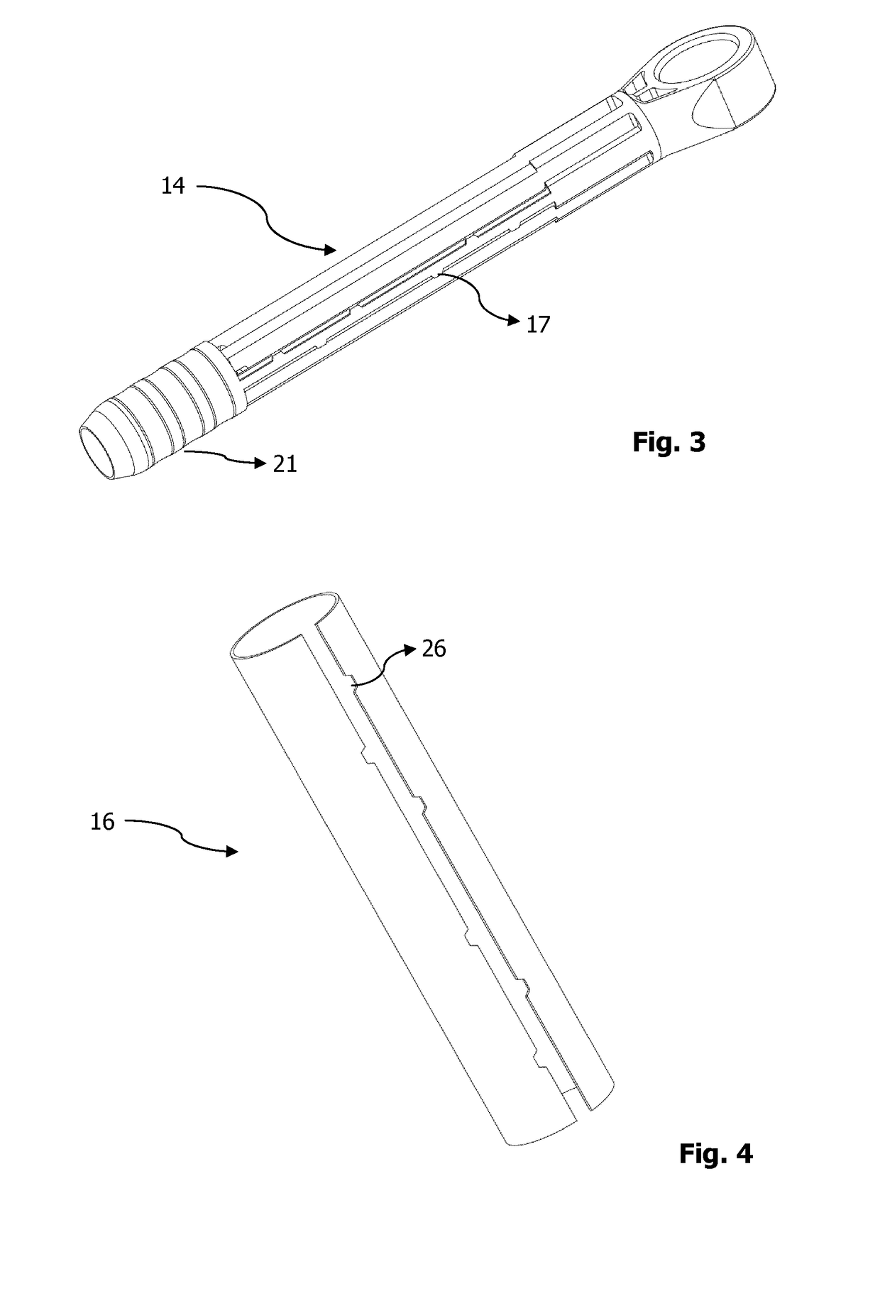
[0034]14. Carrier piece

[0035]15. Piston rod

[0036]16. Tubular body

[0037]17. Carrier piece connection element

[0038]18. Cooling fin

[0039]19. Friction element

[0040]20. Ball-and-socket joint

[0041]21. Wavy surface

[0042]22. Ventilation opening of the piston body

[0043]23. Fitting groove

[0044]24. Piston body

[0045]25. Rectangular ventilation opening

[0046]26. Tubular body connection element

[0047]27. Flexure elements

[0048]28. Gap

[0049]29 Carrier piece connection hole

[0050]30 Halve

[0051]31 Fitting protrusion

[0052]32 longitudinal shrink

[0053]Hereinafter, preferred embodiments of the present invention will be described in detail with reference to the accompanying drawings which are given solely for the purpose of exemplifying embodiments according to the present invention...


PUM


Abstract

A frictional vibration damper for washing machines is disclosed. The damper comprises a piston body and a piston rod which adapted to move along the primary axis of said piston body. A friction element is located in between the piston rod and the piston body. The piston rod and piston body is equipped with joint at one of their ends for connection to the frame and the drum of the washing machine. The piston rod comprises a tubular body which is made of sheet material and which is fixedly rolled around a carrier piece. The frictional damper according to the present invention preferentially comprises, on one or both sides of the tubular body, with connection elements in the longitudinal direction for engaging to corresponding connection elements located on the carrier piece.

Description

TECHNICAL FIELD OF THE INVENTION[0001]The present invention relates to a frictional vibration damper for washing machines, comprising a piston rod which can be telescopically driven in a piston body and a friction element arranged between said piston rod and body for providing a better and less noisy performance of the same during operation.DESCRIPTION OF THE PRIOR ART[0002]The frictional dampers are capable of effectively reducing vibration and used to dampen and absorb the vibrations generated by the washing machine drums. As is known, in washing machine friction dampers, the friction element interposed between the piston rod and piston body which must be axially restrained in order to properly operate for generating a frictional force when the piston moves inside the piston body.[0003]A frictional vibration damper has been disclosed in WO 03 / 074900. According to what has been disclosed, a friction vibration damper wherein two rectangular steel sheets are bent into semi-cylinders ...

Claims


Application Information

Patent Timeline
Patent Type & Authority Patents(United States)
IPC IPC(8): F16F7/09D06F37/20F16F9/32
CPCD06F37/20F16F7/09F16F9/3221
Inventor KANIOZ, CAN
Owner AKSISTEM ELEKTROMEKANIK SANAYI & TICARET LTD STI
Why Eureka
Try Eureka