
System and method for controlling a gas turbine engine

a technology of gas turbine engine and control system, which is applied in the direction of adaptive control, process and machine control, instruments, etc., can solve problems such as errors in estimated basepoints

Active Publication Date: 2017-08-15
RTX CORP
View PDF8 Cites 7 Cited by
  • Summary
  • Abstract
  • Description
  • Claims
  • Application Information

AI Technical Summary

Benefits of technology

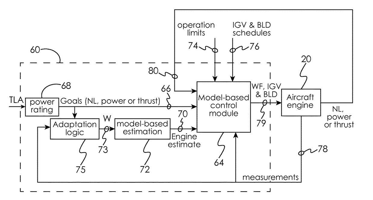
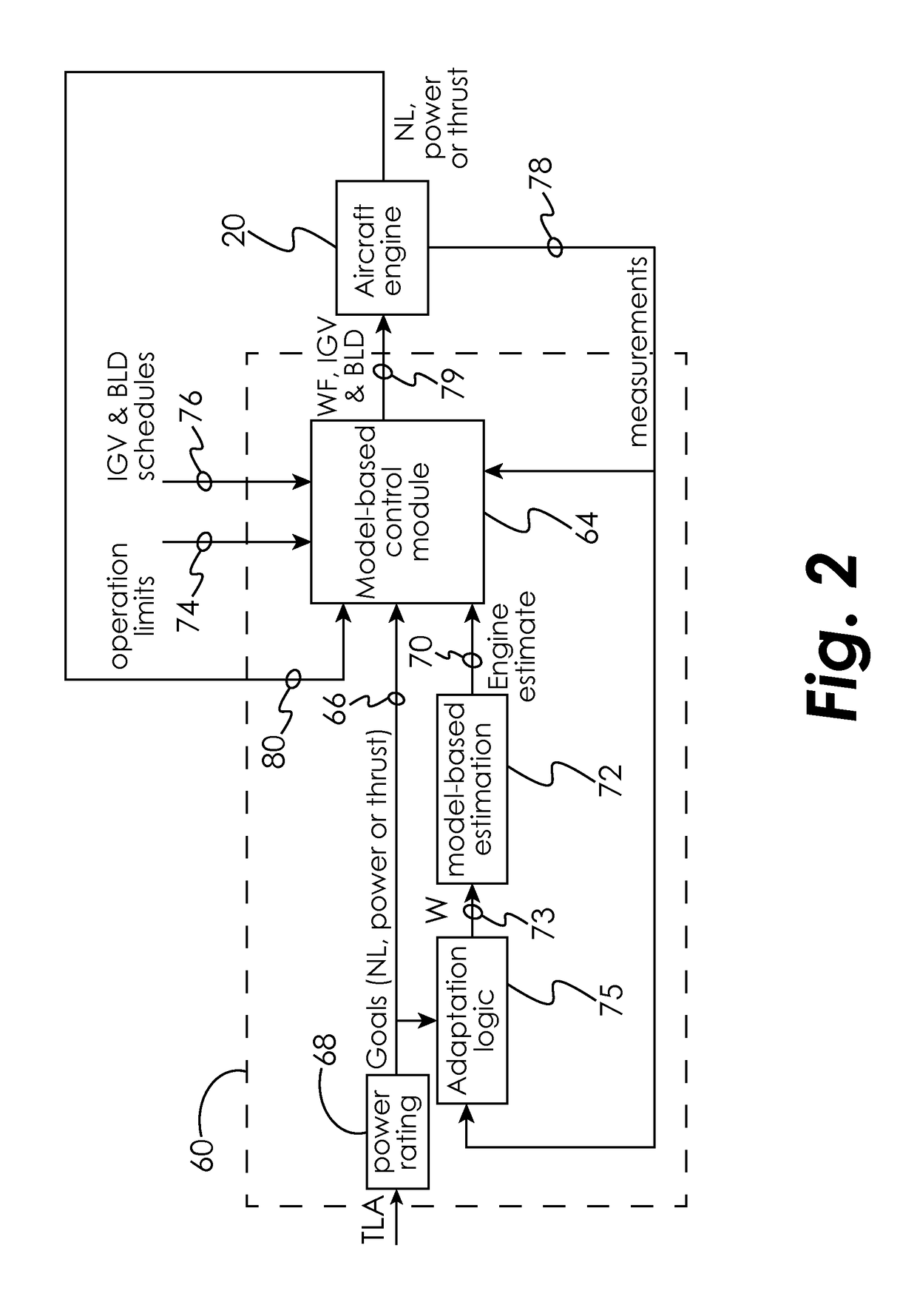
The patent describes a control system for a gas turbine engine that uses a model-based approach to determine the optimal operating parameters for the engine. The system includes sensors that measure various parameters, such as thrust lever angle, power, and inlet guide vane schedules. These signals are combined with a goal signal to create a bandwidth signal, which is then used to estimate the current state of the engine. The system uses this information to determine the fuel flow, inlet guide vane schedules, and stability bleed schedules, and sends signals to the gas generator to control its operation. The system can also use a model-based dynamic inversion methodology to optimize the fuel flow, inlet guide vane schedules, and stability bleed schedules. Overall, the control system provides a more efficient and effective means to control the gas turbine engine's performance.

Problems solved by technology

Such changes can create discrepancies between engine parameters predicted by the control system and corresponding engine parameters measured by the engine sensors, which in turn can create error in the estimated basepoint.

Method used


Image

  • System and method for controlling a gas turbine engine
  • System and method for controlling a gas turbine engine
  • System and method for controlling a gas turbine engine

Examples


Embodiment Construction

[0040]For the purposes of promoting an understanding of the principles of the disclosure, reference will now be made to certain embodiments and specific language will be used to describe the same. It will nevertheless be understood that no limitation of the scope of the disclosure is thereby intended, and alterations and modifications in the illustrated device, and further applications of the principles of the disclosure as illustrated therein are herein contemplated as would normally occur to one skilled in the art to which the disclosure relates.

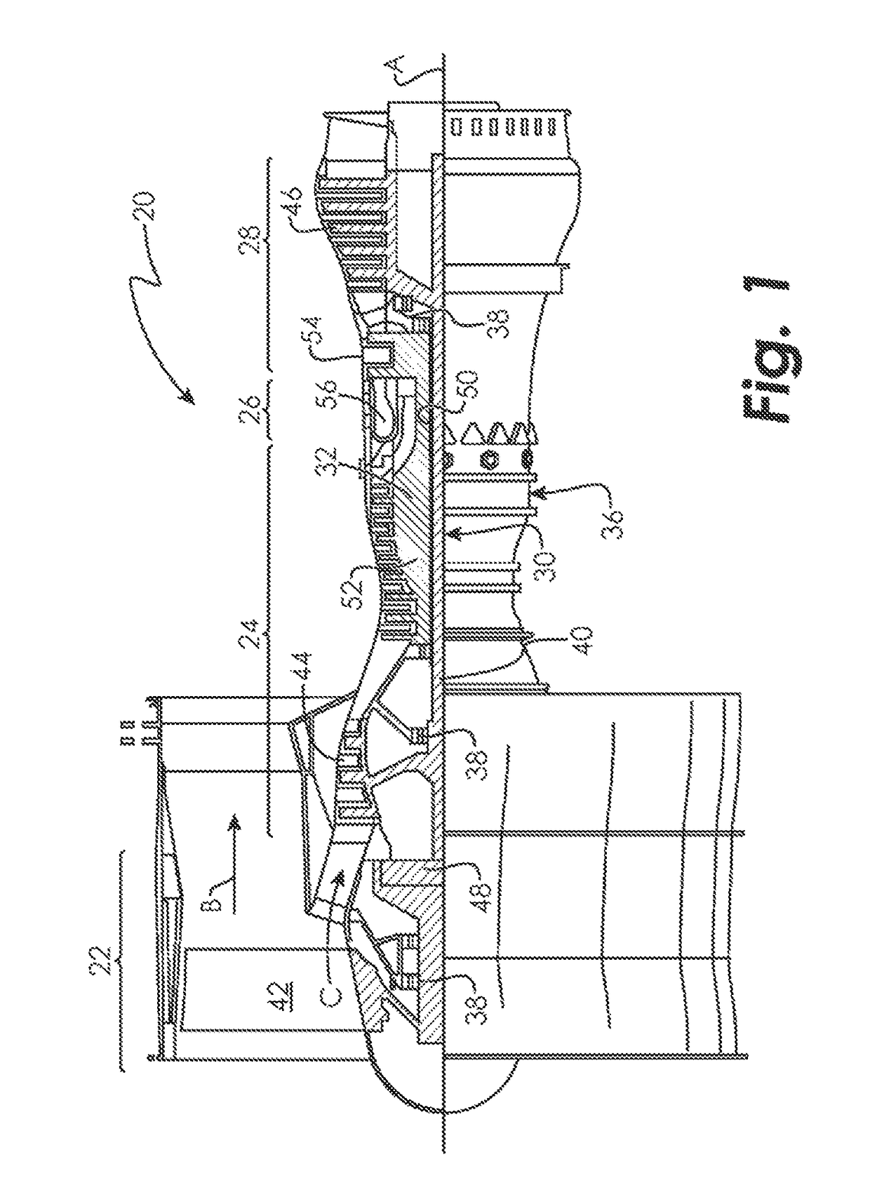
[0041]FIG. 1 schematically illustrates a gas turbine engine 20. The gas turbine engine 20 is disclosed herein as a two-spool turbofan that generally incorporates a fan section 22, a compressor section 24, a combustor section 26 and a turbine section 28. Alternative engines might include an augmentor section (not shown) among other systems or features. The fan section 22 drives air along a bypass flow path B in a bypass duct, while the comp...


PUM


Abstract

A control system for a gas turbine engine including a power turbine is disclosed. The control system may include a control module to receive engine operating goals and an estimated current engine state, wherein the estimated current engine state is produced by a model-based estimation module using a bandwidth signal produced by an adaptation logic module. The control module is operative to determine fuel flow, inlet guide vane schedules and stability bleed schedules based at least in part on the received engine operating goals and the estimated current engine state, and to send signals to a gas generator of the gas turbine engine in order to control the gas generator according to the determined fuel flow, inlet guide vane schedules and stability bleed schedules.

Description

TECHNICAL FIELD OF THE DISCLOSURE[0001]The present disclosure is directed generally toward gas turbine engines, and more specifically toward a control system and method for a gas turbine engine.BACKGROUND OF THE DISCLOSURE[0002]A gas turbine power system can include a control system, a gas turbine engine having a plurality of engine actuators, and a plurality of engine sensors. The control system controls the engine by generating and providing effector signals to the engine actuators. The term “effector signal” is used herein to describe a command signal that controls operation of the engine through the engine actuators.[0003]The effector signals can be generated by processing goals, limits and a basepoint estimate by a control system such that at least some of the goals are satisfied, subject to each limit being held (i.e., no limit is violated). An example of a goal is to operate the engine at a certain thrust level. An example of a limit (i.e., a maximum or minimum) is to prevent...

Claims


Application Information

Patent Timeline
Patent Type & Authority Patents(United States)
IPC IPC(8): F01D21/00F01D17/06G05B13/04F01D17/10
CPCF01D21/003F01D17/06F01D17/105G05B13/048F05D2220/32F05D2240/12F05D2270/304F05D2270/335F05D2270/52F05D2270/62
Inventor CAI, CHAOHONG
Owner RTX CORP
Learn More