
Device and method for an efficient surface evaporation and for an efficient condensation

a technology a device, which is applied in the direction of heat pumps, refrigerating machines, lighting and heating apparatus, etc., can solve the problems of reducing the efficiency of evaporation or condensation, and overheating of up vapor, etc., to achieve the effect of increasing the evaporation efficiency, increasing the power, and increasing the efficiency

Active Publication Date: 2017-08-15
EFFICIENT ENERGY GMBH
View PDF55 Cites 1 Cited by
  • Summary
  • Abstract
  • Description
  • Claims
  • Application Information

AI Technical Summary

Benefits of technology

[0014]At the condenser side, in one embodiment, the condensation efficiency is increased by providing turbulence generators also on the condenser surface, and these turbulence generators lead to a layering of the liquid on the condenser surface being prevented or constantly disrupted. Thus, the warmer top layer which absorbed heat from the condensation process is brought to the bottom and simultaneously cooler liquid in the condenser is brought to the top to be heated up by the condensing vapor. In another embodiment, on the condenser side a laminarization means (means for making laminar) is present which is implemented to make the vapor stream directed to the operating liquid laminar. Thus, an advantageous temperature distribution of the vapor in the laminarization means is achieved, so that a high condenser efficiency is achieved which occurs virtually independently of the temperature with which the vapor enters the condenser space. This is an advantage in particular with heat pumps with compressors, as typically vapor overheating exists which normally, without the use of a laminarizer, leads to a drastic reduction of the condenser efficiency, which is why vapor coolers are used in conventional technology. All such measures are no longer needed due to the laminarizer, as the laminarizer automatically generates a temperature profile which leads to an optimum efficiency. In one embodiment both turbulence generators and also a laminarizers are used on the condenser side, which leads to a further increase of the condenser efficiency.
[0017]Using simplest measures the present invention achieves a substantial increase of the evaporation efficiency and the condenser efficiency, wherein this increase may either be used to manufacture an evaporator or condenser with a higher power. Alternatively, it is however advantageous to use this substantial efficiency increase to construct an evaporator and a condenser substantially smaller and more compact, wherein, however, a certain performance is achieved. This is a great advantage, in particular for an application in a heat pump for heating a building for small and medium-sized buildings, as in buildings, and particularly in residential buildings, space is typically limited. In addition to that, a reduction of the size, due to the reduced amount of material and the easier manageability during manufacturing, leads to substantial cost savings, which is of special importance particularly for the use in heat pumps which may be manufactured on a large scale and have to be of a reasonable price for the individual clients. At the same time, turbulence generators and laminarizers may be implemented with the simplest means, thereby avoiding the use of any electronic / electric elements.

Problems solved by technology

Apart from that, with the evaporator of a heat pump there is still the problem that the compressed and heated-up vapor may be overheated, which means that in spite of the fact that the vapor meets the liquid to be heated up the heat transmission from vapor into liquid is limited.
All of these problems lead to the fact that the efficiency when evaporating or condensing is reduced.

Method used


Image

  • Device and method for an efficient surface evaporation and for an efficient condensation
  • Device and method for an efficient surface evaporation and for an efficient condensation
  • Device and method for an efficient surface evaporation and for an efficient condensation

Examples


Embodiment Construction

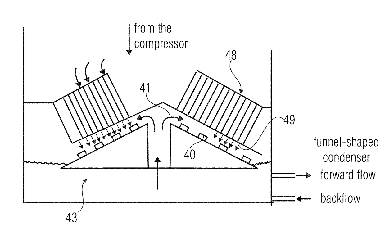
[0034]According to the invention, on the evaporator side and / or on the condenser side, a means for generating vortexes is provided. This water vortex generating means which may comprise a plurality of so-called vortex generators 40, as is illustrated in FIG. 4a and FIG. 4b, leads to the water current 41 leading to a liquid layer on a funnel-shaped evaporator 42 or a funnel-shaped condenser 43 passing across the vortex generators. This leads to the water stream which is to be evaporated or condensed being continuously subjected to turbulence or vortexes. Thus, the bottom layer of the water film is continuously mixed with the top layer of the water film.

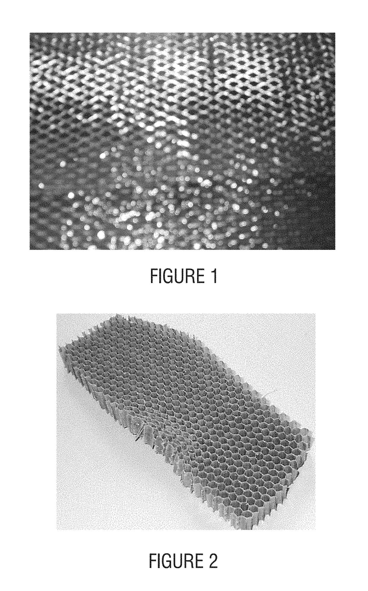
[0035]For so-called vortex generators, different materials may be used, like, for example, a wire mesh fence, as is schematically illustrated in FIG. 1. This wire mesh fence is arranged in the water stream or water current so that the wire represents an obstacle for the water current and continuously leads to a division of the flow and...


PUM


Abstract

An evaporator or a condenser includes a surface on which the operating liquid is arranged. Further, turbulence generators are provided to generate turbulences in the operating liquid located on the operating surface. In the condenser, alternatively or additionally, a laminarizer is present to make the vapor stream laminar provided by the compressor. On the evaporator side, the evaporation efficiency is increased and, on the condenser side, the condenser efficiency is increased, which may be used for a substantial reduction in size without loss of power of these components, in particular for a heat pump for heating a building.

Description

CROSS-REFERENCE TO RELATED APPLICATIONS[0001]This application is a divisional of copending U.S. application Ser. No. 12 / 976,230, filed Dec. 22, 2010, which is a continuation of copending International Application No. PCT / EP2009 / 004519, filed Jun. 23, 2009, both of which are incorporated herein by reference in their entirety, and additionally claims priority from German Applications Nos. DE 102008029597.3, filed Jun. 23, 2008 and DE 10 2008 031 300.9, filed Jul. 2, 2008, which are all incorporated herein by reference in their entirety.BACKGROUND OF THE INVENTION[0002]The present invention relates to evaporating or condensing on surfaces and in particular to an application of evaporating and condensing to surfaces in heat pumps.[0003]A liquid layer, as it, for example, occurs in an evaporator of a heat pump, executes, due to the typical layering which may be observed with liquids and in particular with water as an operating liquid, a heat distribution which means that in the evaporato...

Claims


Application Information

Patent Timeline
Patent Type & Authority Patents(United States)
IPC IPC(8): F25B27/00F28F13/12F25B39/00F28F13/18F25B30/02
CPCF25B30/02F25B39/00F28F13/12F28F13/182F25B43/043
Inventor SEDLAK, HOLGERKNIFFLER, OLIVER
Owner EFFICIENT ENERGY GMBH
Learn More