Apparatus for detecting heights of defects on optical glass

a technology of optical glass and apparatus, applied in mechanical apparatus, instruments, machine supports, etc., can solve the problems of inability to adjust the distance between the transmitter a and the receiver, the top of the glass may have defects, and the damage of expensive glasses subsequently placed on the glass

Inactive Publication Date: 2017-08-15
TAIWAN NANO TECH APPL CORP
View PDF6 Cites 0 Cited by
  • Summary
  • Abstract
  • Description
  • Claims
  • Application Information

AI Technical Summary

Problems solved by technology

It is known that top of the glass may have defects (e.g., particles).
Otherwise, an expensive mask subsequently placed on the glass may be damaged by the particles and this is undesired.
However, the conventional apparatus also has a disadvantage of having a fixed distance between the transmitter A and receiver B. That is, an adjustment of the distance between the transmitter A and receiver B is impossible.
Further, particles having a height in the range of 100-150 μm cannot be detected.
Unfortunately, the particles can still damage a mask if the mask is placed on the glass in a subsequent manufacturing step.
Furthermore, a tact time is about 30 seconds and is unacceptable.

Method used


Image

  • Apparatus for detecting heights of defects on optical glass
  • Apparatus for detecting heights of defects on optical glass
  • Apparatus for detecting heights of defects on optical glass

Examples


Embodiment Construction

[0017]Referring to FIGS. 3 to 7, a detection system in accordance with the invention comprises a detection apparatus 1 and a control console 2 as discussed in detail below.

[0018]The control console 2 includes a personal computer (PC) 20 having a display screen 21, and a controller 22 electronically connected to the PC 20. Signals can be sent from the controller 22 to the PC 20 or vice versa.

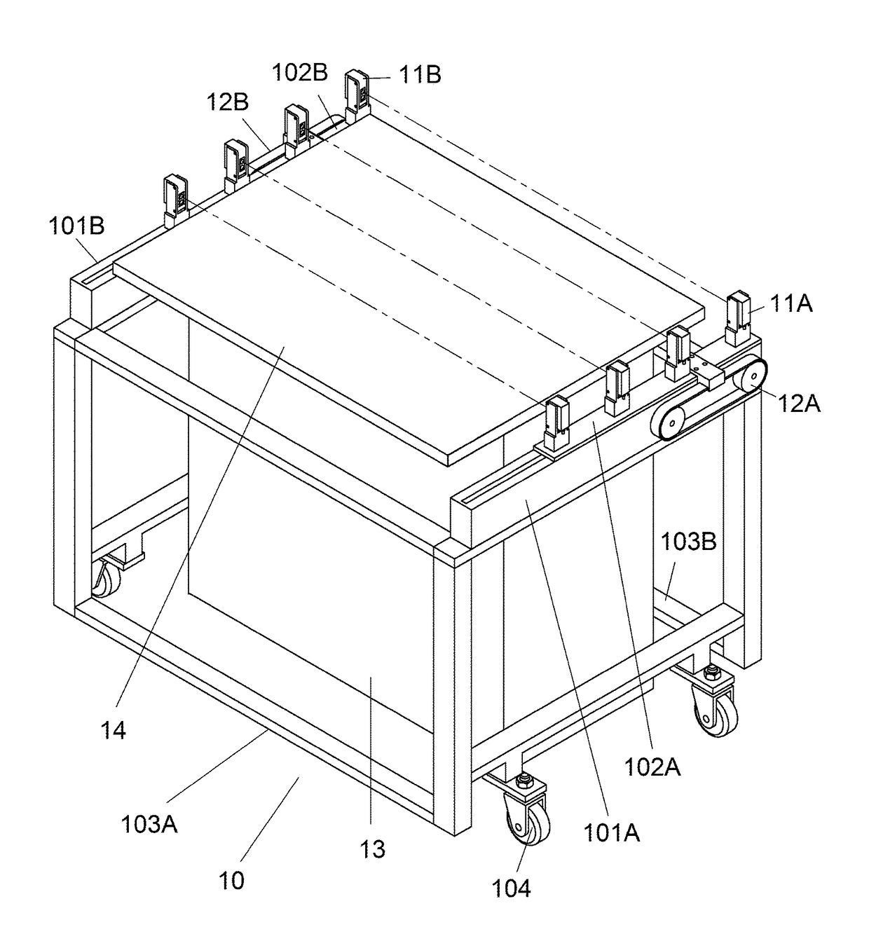
[0019]The detection apparatus 1, as the subject of the invention, includes a frame 10 having two parallel supports 101A, 101B on tops of two sides respectively, two sliding members 102A, 102B on the supports 101A, 101B respectively, two front interconnecting members 103A each having two ends releasably secured to front ends of the supports 101A, 101B respectively, two rear interconnecting members 103B having two ends releasably secured to rear ends of the supports 101A, 101B respectively, and four wheels (only three are shown) 104 rotatably mounted on bottoms of the supports 101A, 101B; four sets...


PUM

PropertyMeasurementUnit
distanceaaaaaaaaaa
distanceaaaaaaaaaa
heightsaaaaaaaaaa

Abstract

A detection apparatus includes four sets of transmitter and receiver wherein the transmitters are on a first sliding member of a frame and the receivers are on a second sliding member of the frame; and drives for moving the first and second sliding members back and forth. During the movements of the first and second sliding members, each transmitter emits laser beam toward the receiver of the same set by passing through a space above a photoresist-coated optical glass by 100 μm, no signal is generated at the receiver if the laser beam is not blocked, and a signal is generated at the receiver if the laser beam is blocked by at least one of a plurality of particles on the photoresist-coated optical glass.

Description

BACKGROUND OF THE INVENTION[0001]1. Field of the Invention[0002]The invention relates to semiconductor device fabrication and more particularly to an apparatus for detecting heights of particles on a photoresist-coated optical glass in the steps of photolithography.[0003]2. Description of Related Art[0004]As shown in FIG. 1, conventional photolithography includes several steps in sequence. For example, after drying and cooling a photoresist-coated optical glass (glass in short), exposure and developing steps are performed on the glass. It is known that top of the glass may have defects (e.g., particles). It is also known that heights of particles on the glass are required to be less than a set value, for example, 100 μm. Otherwise, an expensive mask subsequently placed on the glass may be damaged by the particles and this is undesired. Thus, an apparatus for detecting heights of particles on a glass in the steps of photolithography is required.[0005]A conventional apparatus for dete...

Claims


Application Information

Patent Timeline
Patent Type & Authority Patents(United States)
IPC IPC(8): G01B11/06F16M11/04F16M11/18G01N15/02G01N15/00
CPCG01B11/0608F16M11/048F16M11/18G01N15/0205G01N2015/0061
Inventor TSAI, HONG-IMU, CHANG-CHIEN
Owner TAIWAN NANO TECH APPL CORP
Why Eureka
Try Eureka