Optical lens, camera module group and assembly method thereof

An optical lens and camera module technology, applied in optics, optical components, installation, etc., can solve problems such as skew, poor machining accuracy, and complicated products

Inactive Publication Date: 2016-05-04
NINGBO SUNNY OPOTECH CO LTD
View PDF16 Cites 44 Cited by
  • Summary
  • Abstract
  • Description
  • Claims
  • Application Information

AI Technical Summary

Problems solved by technology

The manufacturing accuracy of the above assembly spacers and diaphragms is much lower than that of the lenses, and there is a risk of assembly deviation between the lenses connected by spacers and pressure rings. The processing accuracy is poor or the thickness is large, which is easy to generate stray light in the optical system. Affect the imaging quality, or due to the tolerance of each component or poor assembly technology, problems such as lens eccentricity or skew occur, which in turn affects the optical performance of the lens module
Moreover, the production of products according to the above-mentioned steps is relatively complicated, with many processes, high cost, difficult to control the quality of finished products, and unable to improve production capacity and yield
[0003] In addition, when assembling a traditional lens, multiple lenses need to be connected with a spacer, and the spacer needs to occupy a certain amount of space, which increases the size of the lens and further increases the size of the module, which not only consumes raw materials, but also is not conducive to product development. The direction of thinning and thinning is developing, and glue must be used to fix the lens, and only a single lens component can be fixed by dispensing at a time, which leads to low production efficiency and further leads to high production costs

Method used


Image

  • Optical lens, camera module group and assembly method thereof
  • Optical lens, camera module group and assembly method thereof
  • Optical lens, camera module group and assembly method thereof

Examples


Embodiment Construction

[0088] The following description serves to disclose the present invention to enable those skilled in the art to carry out the present invention. The preferred embodiments described below are only examples, and those skilled in the art can devise other obvious variations. The basic principles of the present invention defined in the following description can be applied to other embodiments, variations, improvements, equivalents and other technical solutions without departing from the spirit and scope of the present invention.

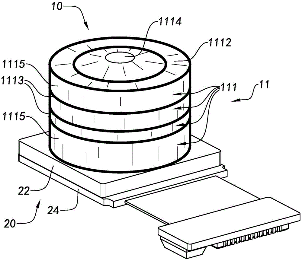
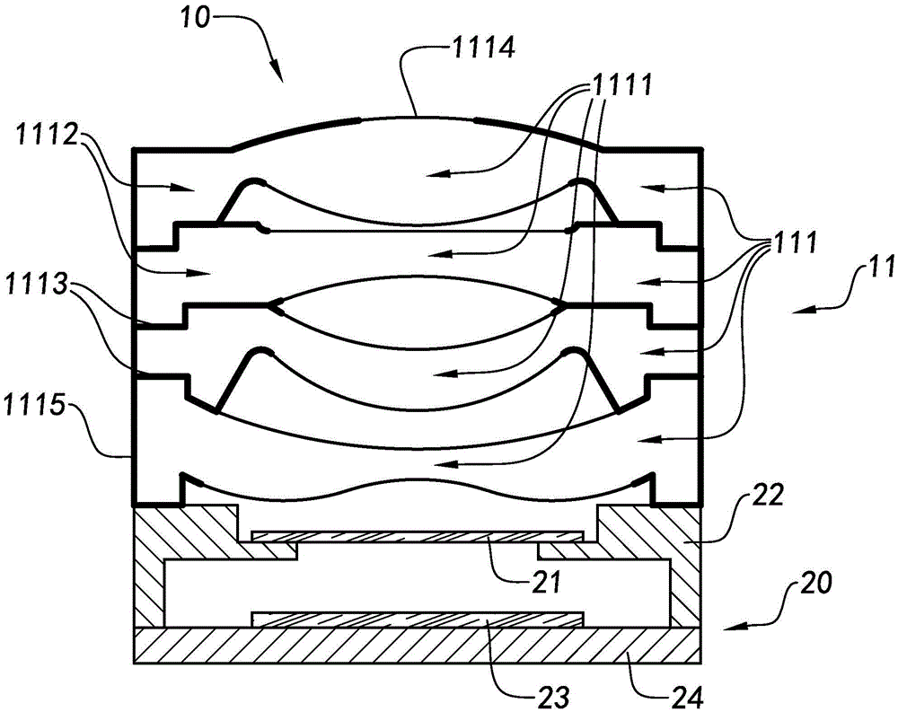
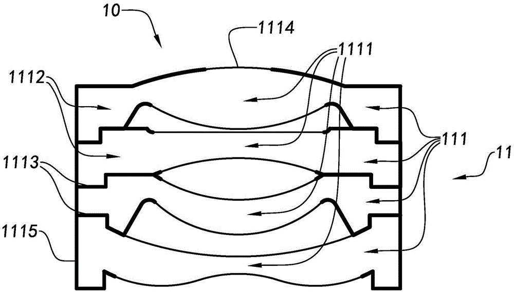
[0089] refer to Figure 1A to Figure 4 , the first specific embodiment of the optical system structure provided by the present invention will be clarified. Such as Figure 1A to Figure 4 As shown, a camera module includes an optical lens 10 and a photosensitive device 20, and the photosensitive device 20 adopts a COB (chiponboard) process to manufacture, including a color filter 21, a mirror holder 22, a photosensitive chip 23 and a A circuit board 24,...


PUM


Abstract

The present invention discloses an optical lens, a camera module group and an assembly method thereof. The camera module group comprises a sensitization chip and an optical lens; the optical lens includes a plurality of optical glasses, wherein the assembly position one optical glass is adjustable, and the blacking extinction processing of each optical glass is performed; and a connection part, a light beam incidence aperture and a shielding part are formed on corresponding optical glasses so as to embed and assemble each optical glass together in order, therefore parts such as a spacing ring, a diaphragm, a lens barrel structure piece and the like used in a traditional camera module group are omitted, and the manufacture precision, the yield rate and the imaging quality of the camera module group are improved.

Description

technical field [0001] The invention relates to the field of camera modules, in particular to an optical lens, a camera module and an assembly method thereof. Background technique [0002] In the conventional camera module assembly process, the lens is an independently assembled part, which includes a lens barrel (including a diaphragm), a lens, a spacer, a stopper, and other structures. The assembly process includes: placing the spacer with the The lenses are loaded into the lens barrel in order, the spacer is pressed on the lens, the spacer and the side wall of the lens barrel are fixed by dispensing glue, and the last lens is fixed with glue or a pressure ring to complete the assembly of the lens. The manufacturing accuracy of the above assembly spacers and diaphragms is much lower than that of the lenses, and there is a risk of assembly deviation between the lenses connected by spacers and pressure rings. The processing accuracy is poor or the thickness is large, which i...

Claims


Application Information

Patent Timeline
Patent Type & Authority Applications(China)
IPC IPC(8): G02B7/02H04N5/225
CPCG02B7/021G02B7/025H04N23/55H04N23/57G03B17/12G02B5/005
Inventor 王明珠郭楠蒋恒刘春梅
Owner NINGBO SUNNY OPOTECH CO LTD
Why Eureka
Try Eureka