
Bridge paving device

a technology for bridges and paving devices, which is applied in bridge construction, construction, roads, etc., can solve the problems of the most technical and labor-intensive paving applications of bridges, and achieve the effect of less preparation and more efficient paving of bridges

Active Publication Date: 2017-08-22
GOMACO
View PDF11 Cites 20 Cited by
  • Summary
  • Abstract
  • Description
  • Claims
  • Application Information

AI Technical Summary

Benefits of technology

The present invention is a new way to use a bridge paving machine to pave a bridge faster and with less preparation than previous methods. The technical effect of this invention is to make the paving process more efficient.

Problems solved by technology

Bridge paving is one of the most technical and labor intensive paving applications.

Method used


Image

  • Bridge paving device
  • Bridge paving device
  • Bridge paving device

Examples


Embodiment Construction

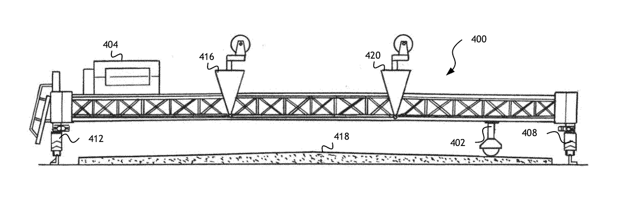
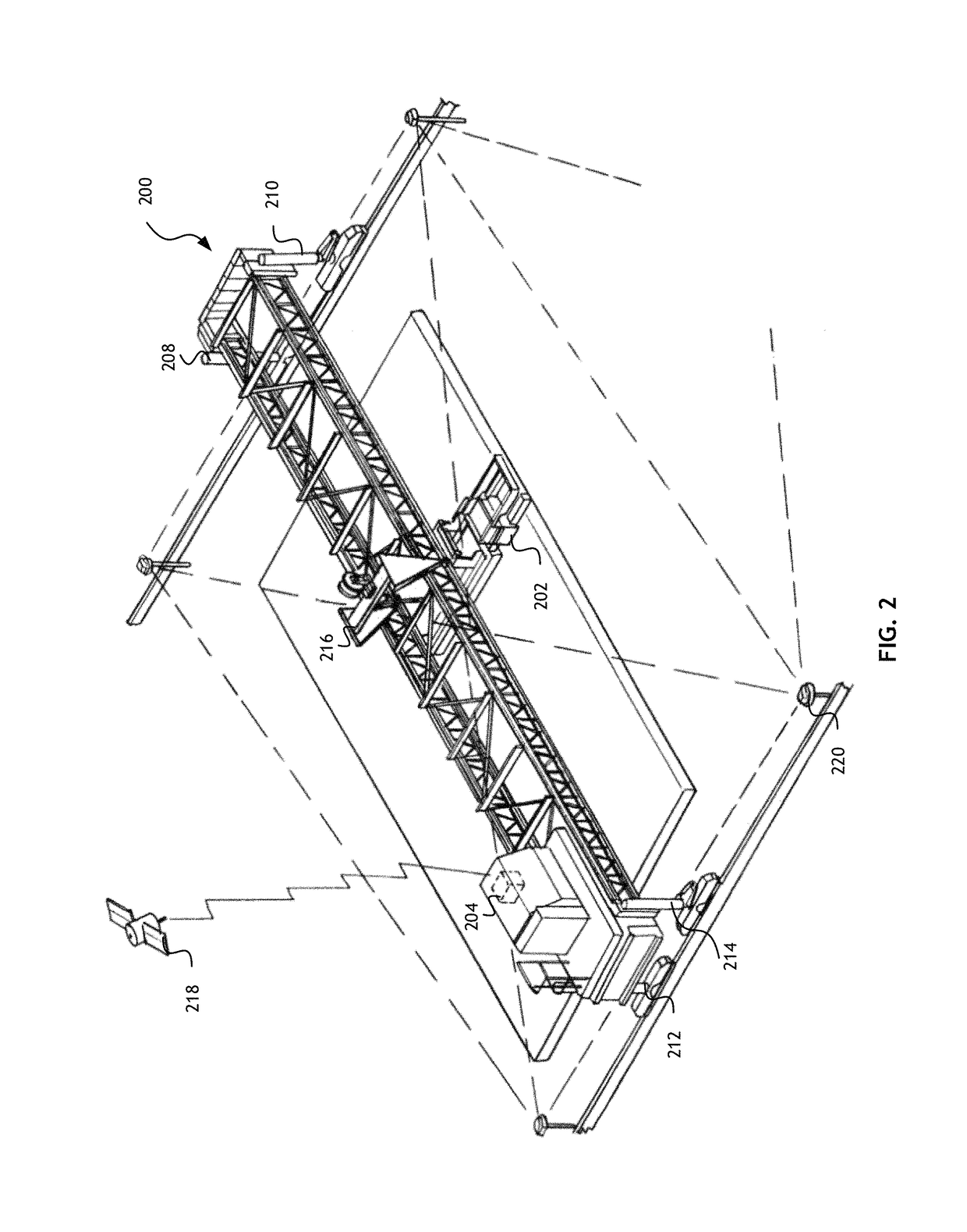
[0018]Reference will now be made in detail to the subject matter disclosed, which is illustrated in the accompanying drawings. The scope of the invention is limited only by the claims; numerous alternatives, modifications and equivalents are encompassed. For the purpose of clarity, technical material that is known in the technical fields related to the embodiments has not been described in detail to avoid unnecessarily obscuring the description.

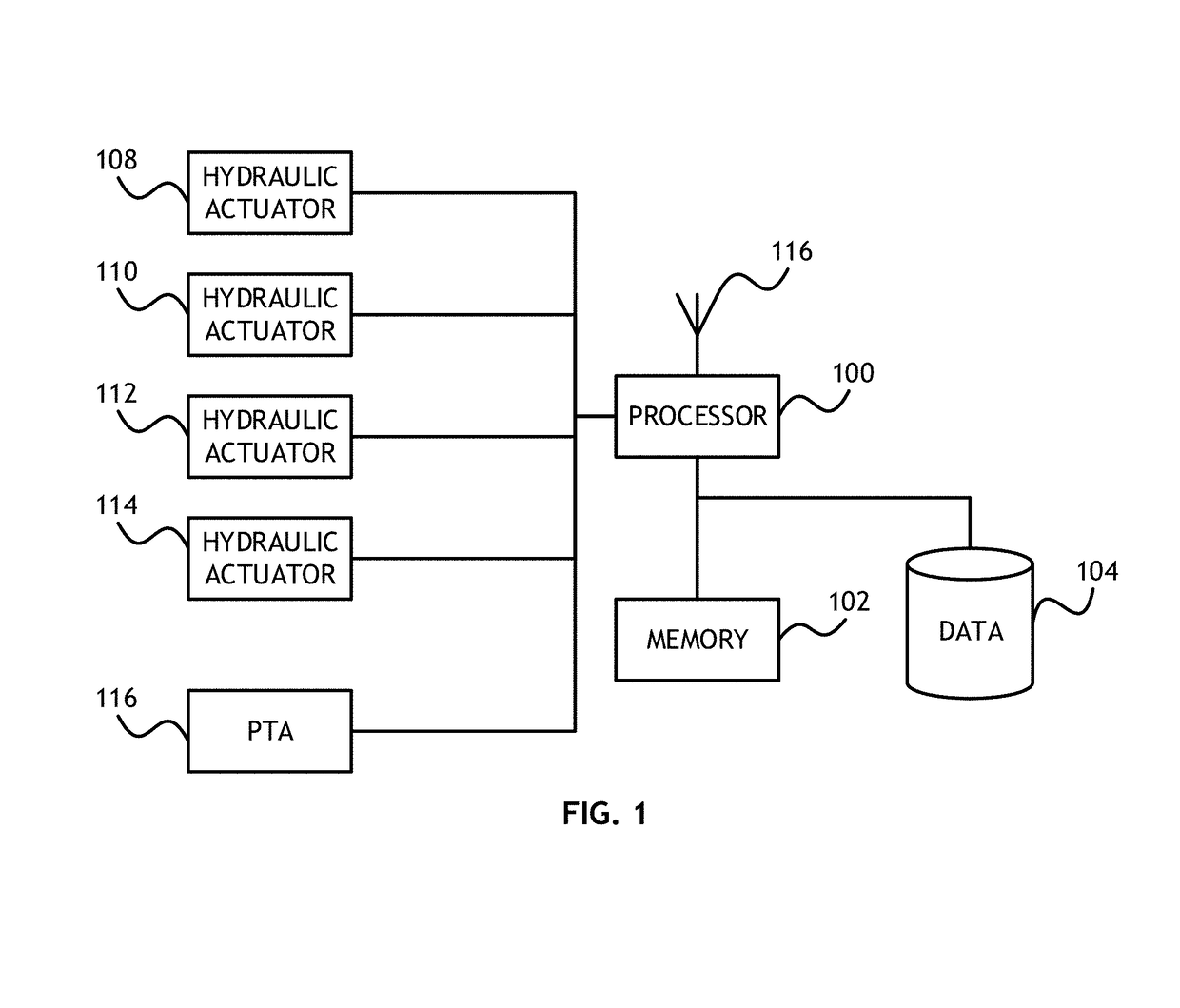
[0019]Referring to FIG. 1, a block diagram of a computer apparatus according to one embodiment of the present invention is shown. In at least one embodiment, a bridge paving device includes a processor 100, memory 102 connected to the processor 100 for storing computer executable program code and a data storage element 104 configured to store a bridge paving profile.

[0020]The processor 100 may also be connected to an antenna 106. The antenna 106 may be configured to receive location data from a surveying instrument such as a Total Station. Al...


PUM


Abstract

A bridge paving device includes one or more reference receivers to locate the bridge paving device in three-dimensional space. A computer apparatus receives the location of the bridge paving device and associates the location with a bridge paving design profile. The computer apparatus independently actuates a system of hydraulic actuators of the bridge paving device to level and orient the bridge paving device regardless of the travel surface the linear movement elements are running on. Additional hydraulic actuators may adjust the shape of the bridge paving device over time as the bridge paving device travels a linear distance of the bridge to be paved. The shape adjustment alters a crown or inversion applied to the bridge such that run-off characteristics are more variable and controllable along the entire span of the bridge.

Description

PRIORITY[0001]The present application claims the benefit under 35 U.S.C. §119(e) of U.S. Provisional Application Ser. No. 62 / 011,687, filed Jun. 13, 2014, which is incorporated herein by reference.FIELD OF THE INVENTION[0002]The present invention is directed generally toward paving machines, and more particularly toward paving machines having cylinder finishers.BACKGROUND OF THE INVENTION[0003]Bridge paving is one of the most technical and labor intensive paving applications. Typically, once the structure of a bridge is in place, guide elements are placed along the periphery of the area to be paved. The guide elements define a reference, and possibly a useable surface, for the linear movement elements of a paving machine.[0004]Because the guide elements define a reference from which all paving operations will be measured, the guide elements must be positioned very precisely. Often, paving crews spend weeks or months surveying and confirming the location of each guide element to ensu...

Claims


Application Information

Patent Timeline
Patent Type & Authority Patents(United States)
IPC IPC(8): E01C19/22E01D19/12E01C9/00E01C19/50E01C19/48E01C7/00E01C19/00E01D21/00
CPCE01C19/004E01C7/00E01C19/4886E01C19/502E01C9/001E01C19/22E01D19/125E01D21/00E01C19/40
Inventor GODBERSEN, GARY L.
Owner GOMACO
Learn More