
Moulding material for composite panels

a composite panel and moulding technology, applied in the direction of synthetic resin layered products, transportation and packaging, chemistry apparatus and processes, etc., can solve the problems of higher differential in fibre modulus, more pronounced problem in carbon composites, and late paint defects in surface layers, so as to reduce resin rich zones, reduce shrinkage and distortion, and improve the effect of quality

Active Publication Date: 2018-02-15
GURIT (UK) LTD
View PDF6 Cites 9 Cited by
  • Summary
  • Abstract
  • Description
  • Claims
  • Application Information

AI Technical Summary

Benefits of technology

The present invention provides a method for making a high-quality fiber reinforced resin matrix composite material with a thinner and more uniform surface resin layer that requires less preparation for painting. This method involves using a prepreg material made of carbon fiber and a resin, which is placed in a heated mold and then subjected to a vacuum and pressure to cause the resin to infuse into the carbon fiber while filtering out the excess resin and filler material. The resulting composite material has exceptional surface finish, stiffness, and strength-to-weight ratios and requires less preparation for painting. Additionally, this method allows for the formation of lightweight and cost-effective composite materials that do not have asymmetrical responses to applied thermal or mechanical loads.

Problems solved by technology

B-Staged or hot-melt resin is preferred to solvent cast resins, as solvent cast resins can lead to entrapped solvent causing later paint defects in the surface layer.
This problem is more pronounced in carbon composites where there is a higher differential in the fibre modulus and thermal expansion of the fibre than the resin.
Thus, such films add undesirable weight to the composite.
However, the inclusion of the suface layer on the B-surface adds further weight.
However, both of the above-mentioned options add weight and cost to the carbon laminate.

Method used

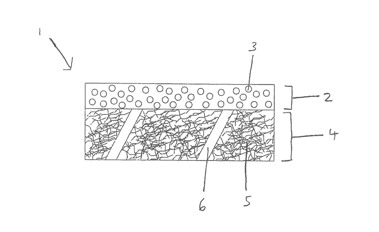
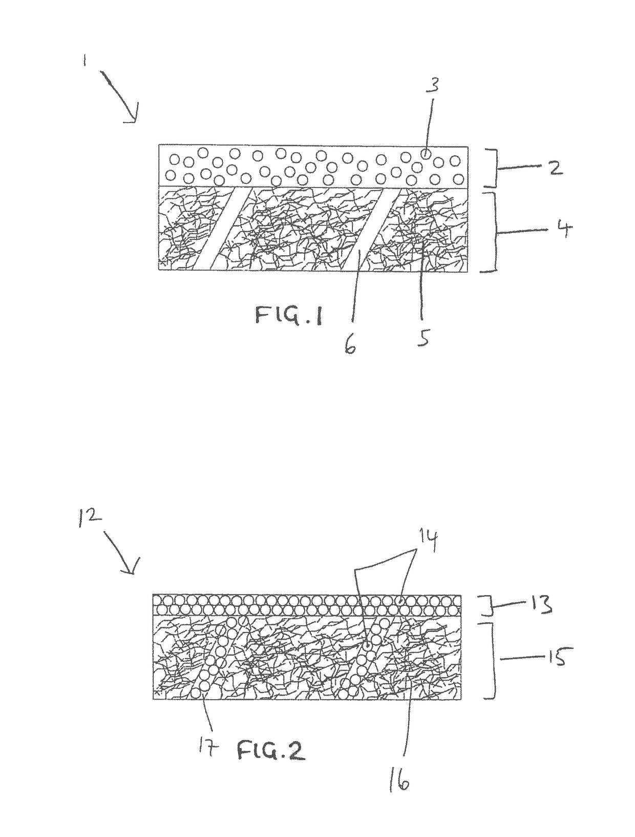
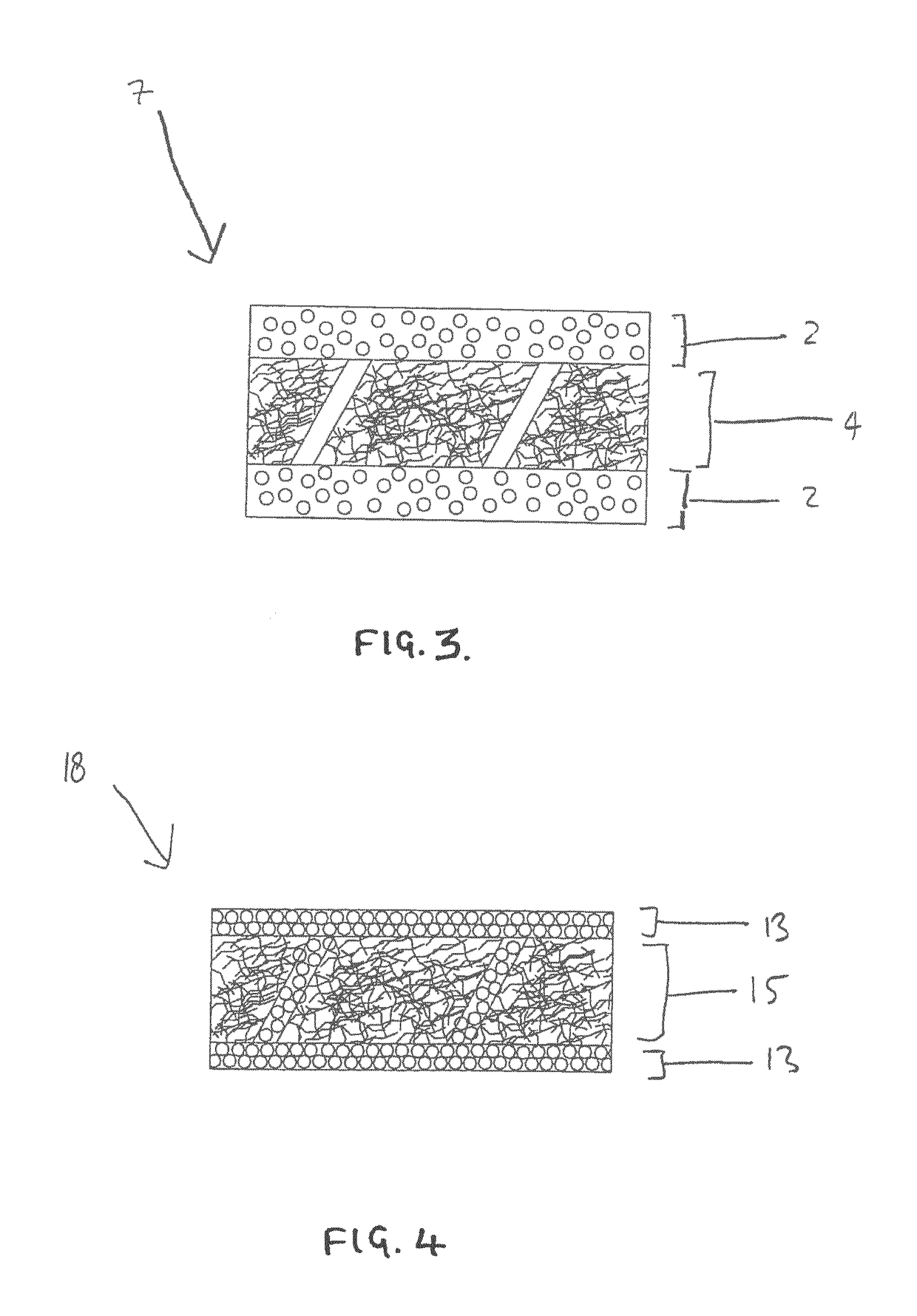

Image

  • Moulding material for composite panels
  • Moulding material for composite panels
  • Moulding material for composite panels

Examples


example 1

[0132]A preform was manufactured and press-cured. The preform consisted of 3 plies of prepreg material:[0133]1. a prepreg containing a 180 micron surface resin layer weighing 290 gsm and containing 38% pbw (22% by vol) particulate filler in contact with the fibrous layer of material B. The resin side was orientated towards the A-surface of the tool;[0134]2. a syntactic prepreg layer of 800 gsm; and[0135]3. The same prepreg as ply 1 but with the resin side was orientated toward the B-surface of the tool.

[0136]The panel had a measured cured ply thickness of 1.29 mm and weight of 1.63 Kg / m2 after the resin bleed-out from processing. The panel had a flexural modulus of 23.2 GPa and a flexural strength of 437.40 MPa. The panel had the equivalent stiffness of a 0.63 mm steel plate weighing 5.01 Kg / m2, giving a 67% weight saving.

[0137]The panel had a good surface finish. It was prepared for paint using the low surface preparation method and assessed to have an acceptable finish to topcoat ...

example 2

[0138]A preform was manufactured and press-cured. The preform consisted of 4 plies of prepreg material:[0139]1. a prepreg containing a 282 micron surface resin layer weighing 452 gsm and containing 38% pbw (22% by vol) particulate filler in contact with the fibrous layer of material B. The resin side was orientated towards the A-surface of the tool;[0140]2. a prepreg formed of from cast films of ST160 prepreg resin in contact with the fibrous layer of material B to give a prepreg containing 300 gsm resin film containing no particulate filler;[0141]3. the same prepreg as ply 2[0142]4. the same prepreg as ply 1 but with the resin side orientated toward the B-surface of the tool.

[0143]The panel had a good surface finish. It was prepared for paint using the low surface preparation method and assessed to have an acceptable finish to topcoat for an A-class panel.

example 3

[0144]A preform was manufactured and press-cured. The preform consisted of 4 plies of prepreg material:[0145]1. a prepreg containing a 282 micron surface resin layer weighing 452 gsm and containing 38% pbw (22% by vol) particulate filler in contact with the fibrous layer of material B. The resin side was orientated towards the A-surface of the tool;[0146]2. a prepreg formed of from cast films of ST160 prepreg resin in contact with the fibrous layer of material B to give a prepreg containing 450 gsm resin film containing no particulate filler;[0147]3. the same prepreg as ply 2;[0148]4. the same prepreg as ply 1 but with the resin side orientated toward the B-surface of the tool.

[0149]The panel had a good surface finish. It was prepared for paint using the low surface preparation method and assessed to have an acceptable finish to topcoat for an A-class panel.


PUM

PropertyMeasurementUnit
thicknessaaaaaaaaaa
thicknessaaaaaaaaaa
particle sizeaaaaaaaaaa

Abstract

The present invention describes a prepreg for the manufacture of fibre reinforced resin matrix composite materials, the prepreg comprising: a surface film comprising a thermosetting resin and a particulate filler material dispersed therein, and a fibrous layer on which the surface film is disposed, the fibrous layer comprising a plurality of non-woven carbon fibres which are substantially randomly oriented, wherein the fibrous layer has interstices between the carbon fibres dimensioned for absorbing at least a portion of the thermosetting resin during a resin infusion step and filtering at least a portion of the particulate filler material in the surface film to remain in the surface film during the resin infusion step.

Description

FIELD OF THE INVENTION[0001]The present invention relates to a prepreg for the manufacture of fibre reinforced resin matrix composite materials. The present invention also relates to a method for preparing the fibre reinforced resin matrix composite material. In particular, the method of the present invention enables the manufacture of body panels, such as automotive body panels, comprising fibre reinforced resin matrix composite materials, where the body panels have a high quality surface finish.BACKGROUND[0002]In the field of automotive body panels, a significant weight saving can be achieved by replacing current metallic automotive body panels with composite materials. With lower cost tooling, significant savings can be made in lower volume production runs.[0003]High performance body panel parts may be manufactured from preimpregnated materials (known as “prepreg”) as described in EP 1 322 460 and EP 1 128 958, or from uni-directional prepreg layers. Plies of prepreg can be first...

Claims


Application Information

Patent Timeline
Patent Type & Authority Applications(United States)
IPC IPC(8): B29C70/08B32B3/26B32B5/02B32B5/12B32B5/06B32B5/16B32B5/26B32B5/30B32B7/08B32B27/08B32B27/12B32B27/20B32B27/26B32B27/38B29C70/48B32B7/02B32B7/09
CPCB29C70/083B29C70/48B32B3/266B32B5/022B32B5/12B32B5/024B32B5/06B32B5/16B32B5/26B32B5/30B32B7/08B32B27/08B32B27/12B32B27/20B32B27/26B32B27/38B29C70/081B29K2063/00B29K2307/04B29K2105/0872B32B2250/40B32B2260/023B32B2260/046B32B2262/106B32B2264/102B32B2264/101B29K2105/12B32B2307/718B32B2307/546B32B2605/00B32B5/00B32B5/02B32B5/22B32B7/00B32B7/02B32B27/06B32B27/18B32B27/28B32B3/00B32B3/26B32B2262/00B32B2264/00B32B2264/10B32B2307/56B32B2307/726B32B2605/003B32B2605/08B32B2250/00B32B7/09C08J5/243C08J5/249B29C70/021B29C70/06B29C70/46B32B2363/00
Inventor JONES, DANIEL THOMAS
Owner GURIT (UK) LTD
Learn More