Supercharge Your Innovation With Domain-Expert AI Agents!

Electrical junction box and wire harness

a technology of electrical junction box and wire harness, which is applied in the direction of insulated conductors, cables, electric/fluid circuits, etc., can solve the problems of misalignment of sheet metal brackets in one edge region and holes for receiving screws on the housing, so as to improve the workability of assembly

Active Publication Date: 2017-08-22
YAZAKI CORP +1
View PDF8 Cites 1 Cited by
  • Summary
  • Abstract
  • Description
  • Claims
  • Application Information

AI Technical Summary

Benefits of technology

This design enhances assembly workability by ensuring precise positioning and secure fixation of the housing and housing support member, reducing assembly time and errors, and improving the overall attachment process.

Problems solved by technology

Therefore, when the sheet metal bracket is assembled with the housing, the holes to receive the screw on the housing and the sheet metal bracket in the one edge region may be misaligned.

Method used


Image

  • Electrical junction box and wire harness
  • Electrical junction box and wire harness
  • Electrical junction box and wire harness

Examples


embodiment

[0028

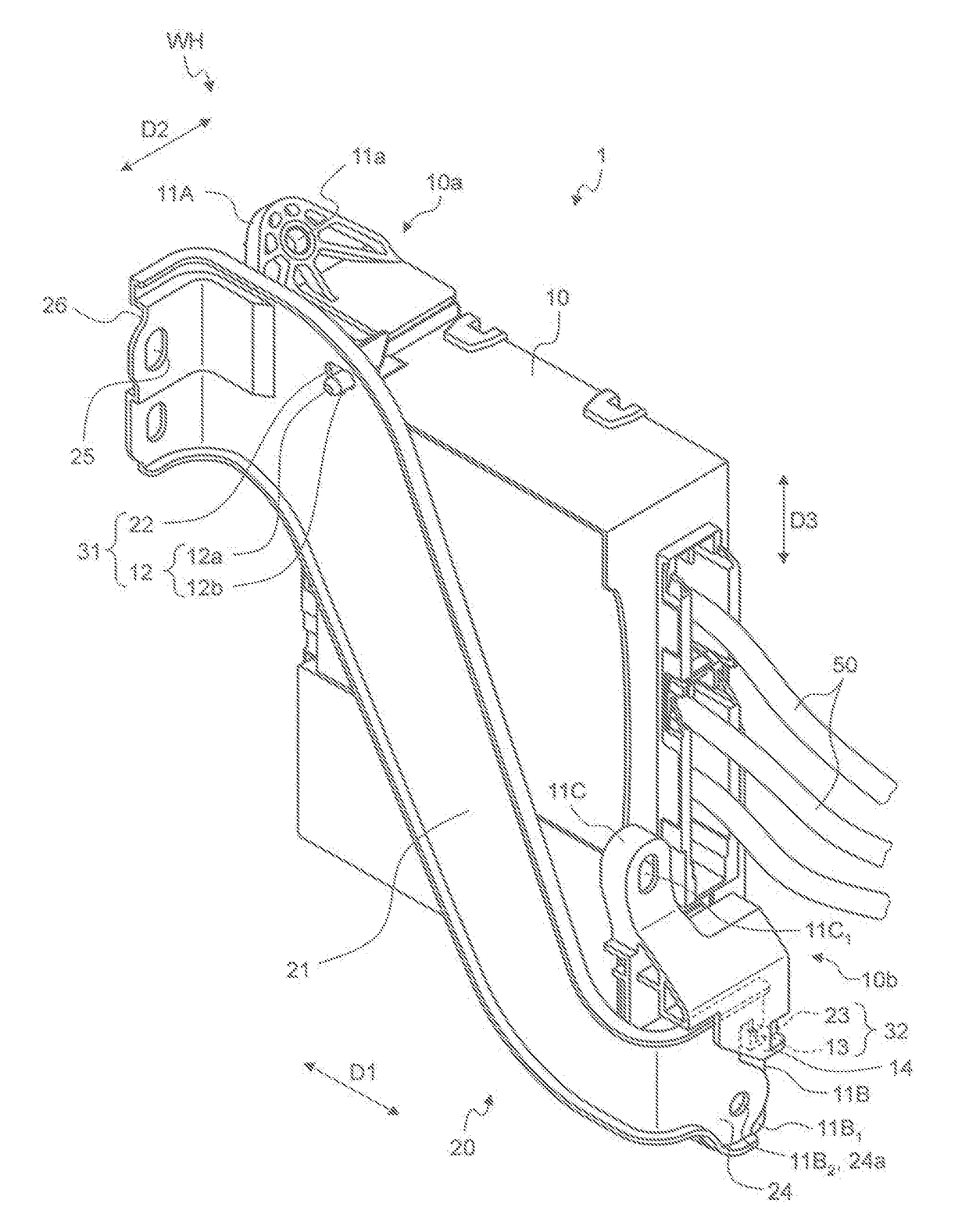
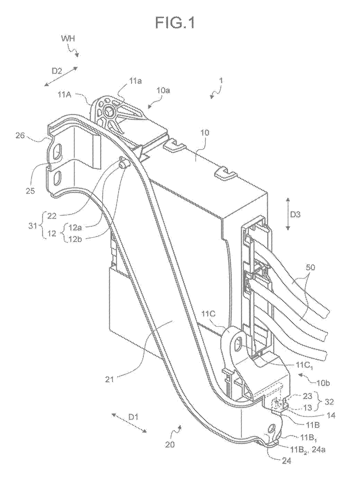
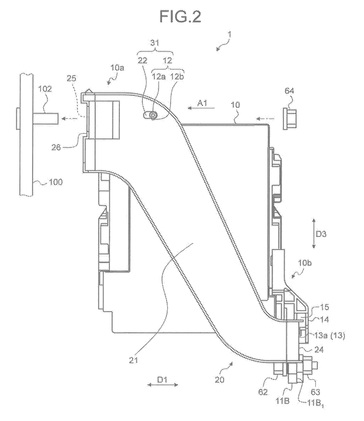
[0029]The electrical junction box and the wire harness according to the embodiment will now be explained with reference to FIGS. 1 to 11.

[0030]The reference numeral 1 in FIGS. 1 to 4 denotes the electrical junction box according to the embodiment. The reference sign WH in FIG. 1 denotes a wire harness having the electrical junction box 1. The electrical junction box 1 according to the embodiment may be interposed between a power source (secondary battery) and an electronic device both of which are not illustrated, and adjusts the power supplied from the power source to the electronic device, for example. The electrical junction box 1 and the wire harness WH are mounted on the vehicle body serving as an object to be attached 100 (FIGS. 2 and 4), and installed between the power source and the electronic device in the vehicle, for example. The electrical junction box 1 is also capable of passing a detection signal of a sensor not illustrated to a control device, as another example...


PUM

PropertyMeasurementUnit
poweraaaaaaaaaa
shapeaaaaaaaaaa
conductiveaaaaaaaaaa

Abstract

An electrical junction box includes a housing attachable to an object to be attached, a housing support member holding the housing and attachable to the object to be attached, and male and female screw members. The housing support member includes a first portion to be engaged with a first engaging portion in the housing, thereby achieving positioning therewith, a second portion to be engaged with a second engaging portion in the housing, thereby achieving positioning therewith, an extending portion extending between the first and second portions to be engaged, and a through hole provided to an end of the extending portion on the second portion to be engaged side. The housing has a through hole. The through holes are disposed to be concentric in a state that the first and second portions to be engaged are respectively engaged with the first and second engaging portion.

Description

CROSS-REFERENCE TO RELATED APPLICATION(S)[0001]The present application claims priority to and incorporates by reference the entire contents of Japanese Patent Application No. 2015-082562 filed in Japan on Apr. 14, 2015.BACKGROUND OF THE INVENTION[0002]1. Field of the Invention[0003]The present invention relates to an electrical junction box and a wire harness.[0004]2. Description of the Related Art[0005]Conventionally known is an electrical junction box having a parallelepipedal housing, and a sheet-metal bracket extending between two edge regions along a diagonal of the hosing. An example of such an electrical junction box is disclosed in Japanese Patent Application Laid-open No. 2013-046483. The sheet metal bracket is fixed to one of the edge regions of the electrical junction box with a screw. The other edge region of the housing and the sheet metal bracket are together fastened to a vehicle body with a screw member. The electrical junction box is also attached to a vehicle body ...

Claims


Application Information

Patent Timeline
Patent Type & Authority Patents(United States)
IPC IPC(8): H02G3/10H01B7/00H02G3/08B60R16/023
CPCH02G3/083B60R16/0238
Inventor DOI, TEPPEIFUJIMOTO, JOHKAWAKAMI, HIROKI
Owner YAZAKI CORP
Features
  • R&D
  • Intellectual Property
  • Life Sciences
  • Materials
  • Tech Scout
  • Unparalleled Data Quality
  • Higher Quality Content
  • 60% Fewer Hallucinations
Learn More