Hydraulic tube for vehicle

a technology for vehicles and hydraulic tubes, applied in mechanical devices, couplings, transportation and packaging, etc., can solve the problems of reducing increasing the cost, and the complexity of the mold for insert molding, so as to improve the oil leakage prevention effect, increase the structural strength of the connector, and reduce the cost

Active Publication Date: 2017-08-29
HYUNDAI MOTOR CO LTD +1
View PDF16 Cites 0 Cited by
  • Summary
  • Abstract
  • Description
  • Claims
  • Application Information

AI Technical Summary

Benefits of technology

[0016]Various aspects of the present invention are directed to providing a hydraulic tube for a vehicle in which slots and a connector groove which are used in the related art are precluded from a plastic connector fabricated by insert molding. This consequently increases the structural strength of the connector, thereby further improving an oil leakage prevention effect. Cost can also be reduced by the simplification of a mold.
[0017]The present invention is also intended to improve a contact structure between a pipe and a sealer which determines the overall sealing performance of the hydraulic tube so as to have a dual contact structure, thereby improving the overall sealing performance and thus significantly improving the oil leakage prevention effect.
[0026]The first sealer groove may include an enclosed space which is closely defined by the pipe rib, the extension surface, and the perpendicular surface in order to improve a performance of sealing between the pipe and the sealer and an oil leakage prevention effect.
[0028]According to the present invention as set forth above, it is possible to increase the structural strength of the connector in order to prevent the connector from being permanently deformed during the assembly between the pipe and the connector, thereby further improving the oil leakage prevention effect. In particular, since the contact structure between the pipe and the sealer which determines the overall sealing performance of the hydraulic tube is improved so as to have a dual contact structure, it is possible to improve the overall sealing performance of the hydraulic tube and thus significantly improve the oil leakage prevention effect.

Problems solved by technology

However, the slots 12b reduce the structural strength of the connector 12 which is made of plastic, which is problematic.
In particular, this makes a mold for insert molding more complicated and increases cost.
When the connector 12 is permanently deformed in this process, a gap is formed between the pipe11 and the connector 12, which disadvantageously leads to an oil leakage.
This consequently causes a permanent deformation in the portion of the connector groove 12a when the pipe 11 and the connector 12 are assembled together, which disadvantageously leads to an oil leakage.

Method used


Image

  • Hydraulic tube for vehicle
  • Hydraulic tube for vehicle
  • Hydraulic tube for vehicle

Examples


Embodiment Construction

[0036]Reference will now be made in detail to various embodiments of the present invention(s), examples of which are illustrated in the accompanying drawings and described below. While the invention(s) will be described in conjunction with exemplary embodiments, it will be understood that the present description is not intended to limit the invention(s) to those exemplary embodiments. On the contrary, the invention(s) is / are intended to cover not only the exemplary embodiments, but also various alternatives, modifications, equivalents and other embodiments, which may be included within the spirit and scope of the invention as defined by the appended claims.

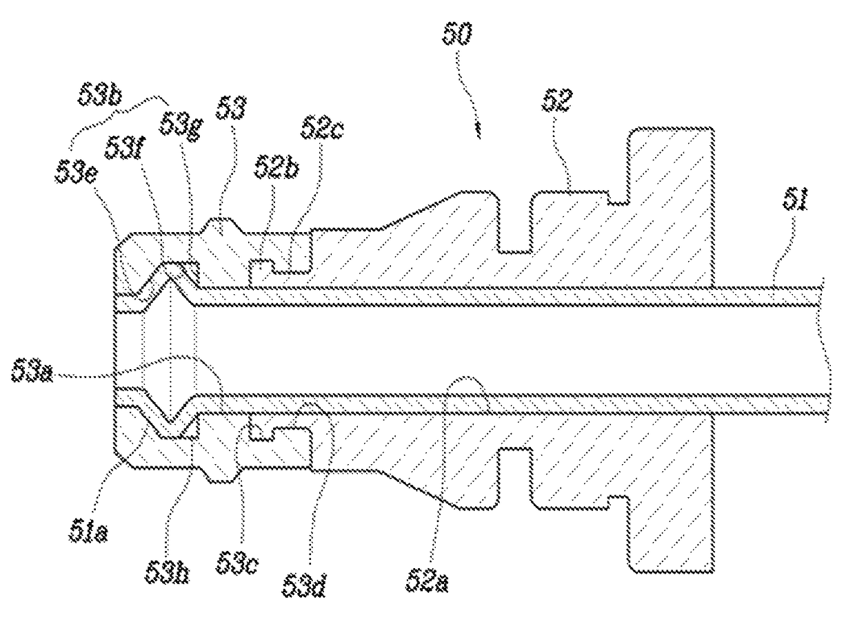
[0037]Reference will now be made in greater detail to a hydraulic tube for a vehicle according to the present invention, an exemplary embodiment of which is illustrated in the accompanying drawings. Wherever possible, the same reference numerals will be used throughout the drawings and the description to refer to the same or like ...


PUM


Abstract

A hydraulic tube for a vehicle may include a pipe having a pipe rib which may be formed integrally on and protrudes outward from a terminal end of the pipe, a connector fitted around the pipe such that the pipe extends through opposite ends of the connector, and a sealer fitted into a first end of the connector, a first end of the sealer being coupled with the terminal end of the pipe through coupling with the pipe rib, and a second end of the sealer being coupled with the first end of the connector.

Description

CROSS-REFERENCE(S) TO RELATED APPLICATION[0001]The present application claims priority of Korean Patent Application Number 10-2013-0160619 filed on Dec. 20, 2013, the entire contents of which application is incorporated herein for all purposes by this reference.BACKGROUND OF THE INVENTION[0002]Field of the Invention[0003]The present invention relates to a hydraulic tube for a vehicle, and more particularly, to a hydraulic tube which has improved performance for preventing oil leakage.[0004]Description of Related Art[0005]Referring to FIG. 1, a clutch system using hydraulic power employs a hydraulic tube 10 which transfers hydraulic power from a clutch master cylinder 1 to a release cylinder 3.[0006]Referring to FIGS. 2A and 2B, the hydraulic tube 10 of the related art includes a pipe 11 made of steel, a connector 12 made of plastic which is fitted into and coupled with the pipe 11, and a sealer 13 made of rubber which is fitted into one end of the pipe 11 and is coupled with one end...

Claims


Application Information

Patent Timeline
Patent Type & Authority Patents(United States)
IPC IPC(8): F16L19/00F16L21/00F16L23/028F16L37/00
CPCF16L21/00F16L23/0283F16L37/00F16L21/035F16L37/088F16L37/144B60K23/02B60R16/08F16D2048/0224
Inventor KIM, BUM JUNKWON, MIN KEUNKIM, EUN SIKCHOO, SEONG HWALIM, JEONG HO
Owner HYUNDAI MOTOR CO LTD
Why Eureka
Try Eureka