
System and method for adaptive positioning of a work piece

a work piece and work piece technology, applied in the field of positioning and securing work pieces, can solve the problems of multiple production of precision manufactured parts, delay and opportunity for errors, multiplied time required and opportunities for errors, etc., to improve process output quality, save setup time, and reduce the probability of errors

Active Publication Date: 2017-08-29
ADVANCED SIMULATION TECH
View PDF16 Cites 1 Cited by
  • Summary
  • Abstract
  • Description
  • Claims
  • Application Information

AI Technical Summary

Benefits of technology

The invention is a measuring apparatus that can accurately measure the shape and dimensions of a work piece in three dimensions. This apparatus is versatile and can be used with different types of work pieces. It uses an adaptive positioning system that can adjust to the unique geometry and dimensions of each work piece, allowing for precise machining. The invention also extends the benefits of adaptive positioning to CNC machines that may not have full movement capabilities, reducing costs and allowing for more efficient manufacturing.

Problems solved by technology

For a work piece that has imprecise dimensions, the dimensions of the work piece vary from work piece to work piece, making the repeatable production of precision manufactured parts problematic.
The problem is that each imprecise work piece defines unique manufacturing constraints to successfully produce the finished part; namely, each edge and surface of the finished part must fall within the volume defined by the work piece.
In addition, the work piece may define additional constraints relating to manufacture or operation of the finished part, such as local internal changes in material specifications or strand orientation in the case of the carbon fiber composite.
A major disadvantage of adaptive machining is that the location of the work piece must be identified and the programming of the CNC machine must be changed with every succeeding work piece, with the resulting delay and opportunity for error.
In addition, a typical machining operation for a complex manufactured part may require multiple sequential steps performed on multiple CNC machines.
With each transfer of the work piece to a new CNC machine, the location and orientation of the work piece must be re-identified with respect to the tool and the programming of the CNC machine must be changed, multiplying the time required and opportunities for error by the number of CNC machines involved and reducing the capabilities of the system to those of the least capable CNC machine.
Another disadvantage is that many CNC machines are not capable of the six degrees of freedom required to take full advantage of adaptive machining.
First, the combination of the CNC machine and the adaptive fixture typically must be customized to a particular type of work piece and thus have very significant monetary and time costs associated with their development, as well as the loss of flexibility since the CNC machine and adaptive fixture combination cannot be used for other types of work pieces.
Second, adaptive fixtures tend either to require tedious and time-consuming manual adjustment or to be bulky electromechanical devices that cannot be easily moved between CNC machines.
The use of adaptive fixtures restricts the flexibility of the CNC machines and significantly increases cost, particularly when using adaptive fixturing on work pieces that require multiple processes on multiple CNC machines.
Third, adaptive fixtures cannot comprehensively measure a part, which means that process adaptations cannot be based on areas of the part that are inaccessible for measurement when the part is in the work-holding position.
Finally, due to prohibitive costs and complexity, adaptive fixtures typically do not have the full six degrees of spatial manipulation necessary to correct for certain positioning and manufacturing imperfections.
The prior art does not teach the work-holding system and method of the Invention.

Method used


Image

  • System and method for adaptive positioning of a work piece
  • System and method for adaptive positioning of a work piece
  • System and method for adaptive positioning of a work piece

Examples


Embodiment Construction

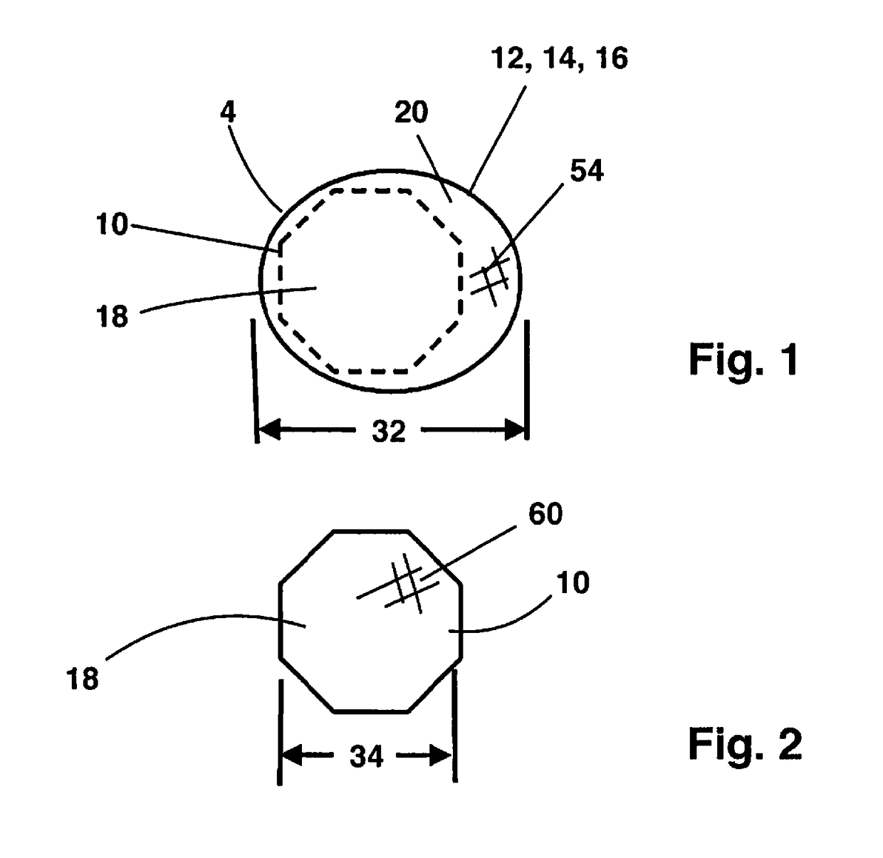
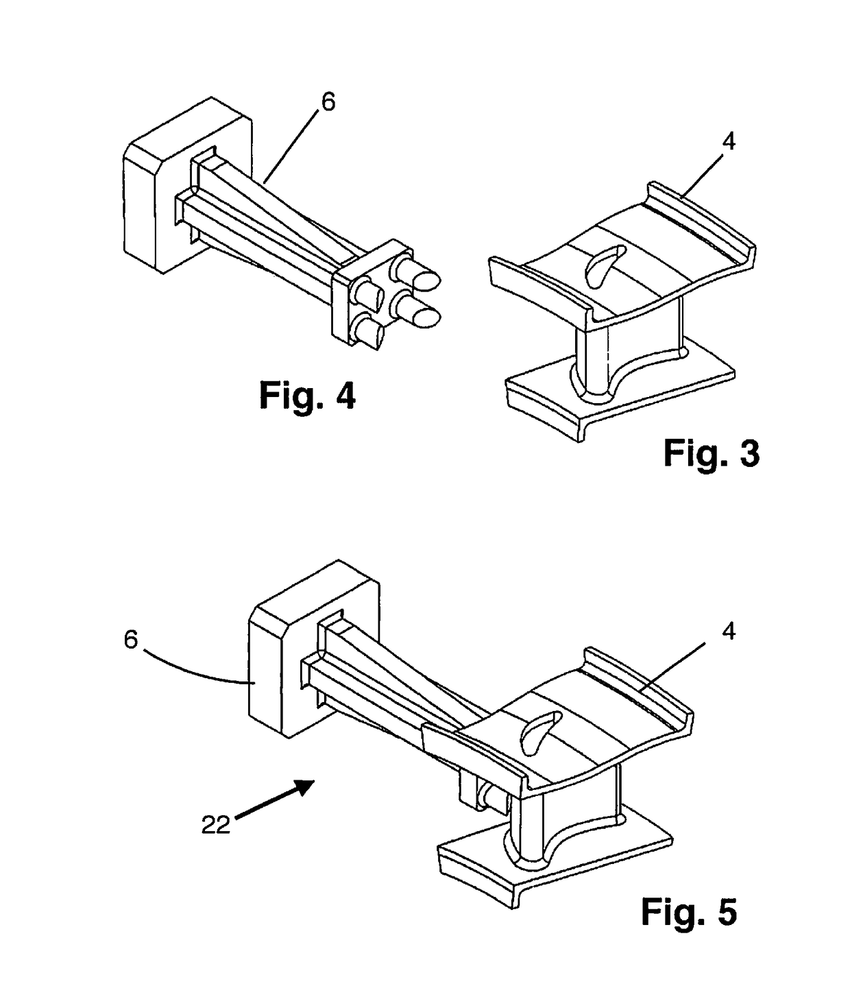
[0049]The invention is an adaptive positioning system 2 for positioning a work piece 4 to a non-adaptive fixture 6 for use on a CNC machine 8 to turn the work piece 4 into a machined object 10. As shown by FIGS. 1 and 2, a CNC machine 8 changes the shape of a work piece 4 to produce the machined object 10. While the system 2 of the invention is most useful for operations on an imprecise work piece 4, such as a casting 12, forging 14 or layup 16, the system 2 is applicable to any work piece 4, regardless of the precision of the work piece 4.

[0050]FIG. 1 shows a section of a work piece 4 and FIG. 2 shows a section of the corresponding machined object 10. Dashed lines on FIG. 1 show the location of the machined object 10 within the work piece 4. The machined object volume 18, including each dimension 34, edge and surface of the machined object 10, must fall within the work piece volume 20 defined by the work piece 4.

[0051]FIG. 3 shows a work piece 4 typical of an aerospace work piece 4...


PUM


Abstract

The Invention is a system and method for adaptively attaching a work piece, especially an imprecise work piece, to a non-adaptive fixture that can be repeatably attached to one or more CNC machines. The Invention allows a work piece to be set up once for multiple machining operations. The Invention avoids the potential for errors and the cost and complexity inherent in adaptive machining and adaptive fixturing.

Description

I. STATEMENT OF RELATED APPLICATIONS[0001]This application is entitled to priority from provisional patent application 62 / 080,282 filed Nov. 15, 2014 with Steven B. Lelinski as the first named inventor. The disclosure of application 62 / 080,282 is hereby incorporated by reference herein.II. BACKGROUND OF THE INVENTION[0002]A. Field of the Invention[0003]The Invention relates to positioning and securing a work piece for accurate shaping of the work piece using computer numerical controlled (CNC) machines. Specifically, the Invention relates to the adaptive positioning and securing of an imprecise work piece, such as a casting, forging or composite layup, in a non-adaptive fixture where the fixture may be repeatably attached to the table or stage of one or more CNC machines.[0004]B. Statement of the Related Art[0005]As used in this document, a ‘computer numerical controlled machine,’ or ‘CNC machine,’ refers to a manufacturing apparatus having automated control of any shaping, subtract...

Claims


Application Information

Patent Timeline
Patent Type & Authority Patents(United States)
IPC IPC(8): G05B19/402
CPCG05B19/402G05B2219/42249G05B2219/49124G05B2219/50063G05B2219/50148B23Q17/2291G05B2219/37208B23K37/0426
Inventor JARVIS, MATTHEW T.ROGERS, MARK A.LELINSKI, STEVEN B.POTTER, ALVIN
Owner ADVANCED SIMULATION TECH
Learn More