Intervertebral implant device with independent distal-proximal expansion

a technology of intervertebral implants and distal proximal expansion, which is applied in the field of expandable interbody fusion implant devices, can solve the problems of additional screws or locking elements, the device of a circular shape is not the best fit for the adjacent vertebrae being spaced, and the amount of post insertion manipulation required to reach the height of fully expanded properly, etc., to achieve the effect of preventing loosening

Active Publication Date: 2017-09-05
SPINAL ELEMENTS INC
View PDF25 Cites 65 Cited by
  • Summary
  • Abstract
  • Description
  • Claims
  • Application Information

AI Technical Summary

Benefits of technology

[0017]In a preferred embodiment, the first and second base plates as an optional feature each have, at the proximal end, an end plate with a fastener opening for securing the implant to a vertebral body. Each end plate is integral to and selectively movable with the base plate during expansion or contraction. Each end plate further has a locking tab attached to the end plate, the locking tab being rotatable to cover a portion of the fastener to prevent loosening after being affixed to a vertebral body. These end plates, when incorporated into the base plates, make the implant device of the present invention a unique standalone device.

Problems solved by technology

One of the problems of such devices is the amount of post insertion manipulation required to reach a fully expanded properly space height is tedious and time consuming.
Secondly, additional set screws or locking elements are often required to keep the device at its proper size.
Thirdly, the devices of a circular shape are not the best fit for the adjacent vertebrae being spaced.
Fourth, most of the devices have the internal space occupied with mechanisms limiting the amount of bone growth material available for packing the implants.
This places localized high loading between the vertebrae because the wedge surfaces are not parallel to the vertebrae.
This simply is cost prohibitive.

Method used


Image

  • Intervertebral implant device with independent distal-proximal expansion
  • Intervertebral implant device with independent distal-proximal expansion
  • Intervertebral implant device with independent distal-proximal expansion

Examples


Embodiment Construction

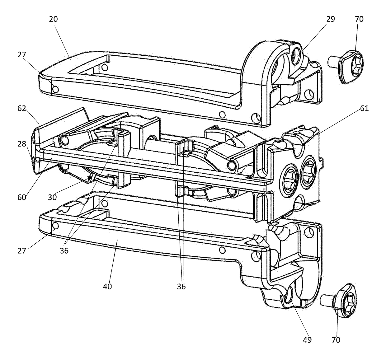
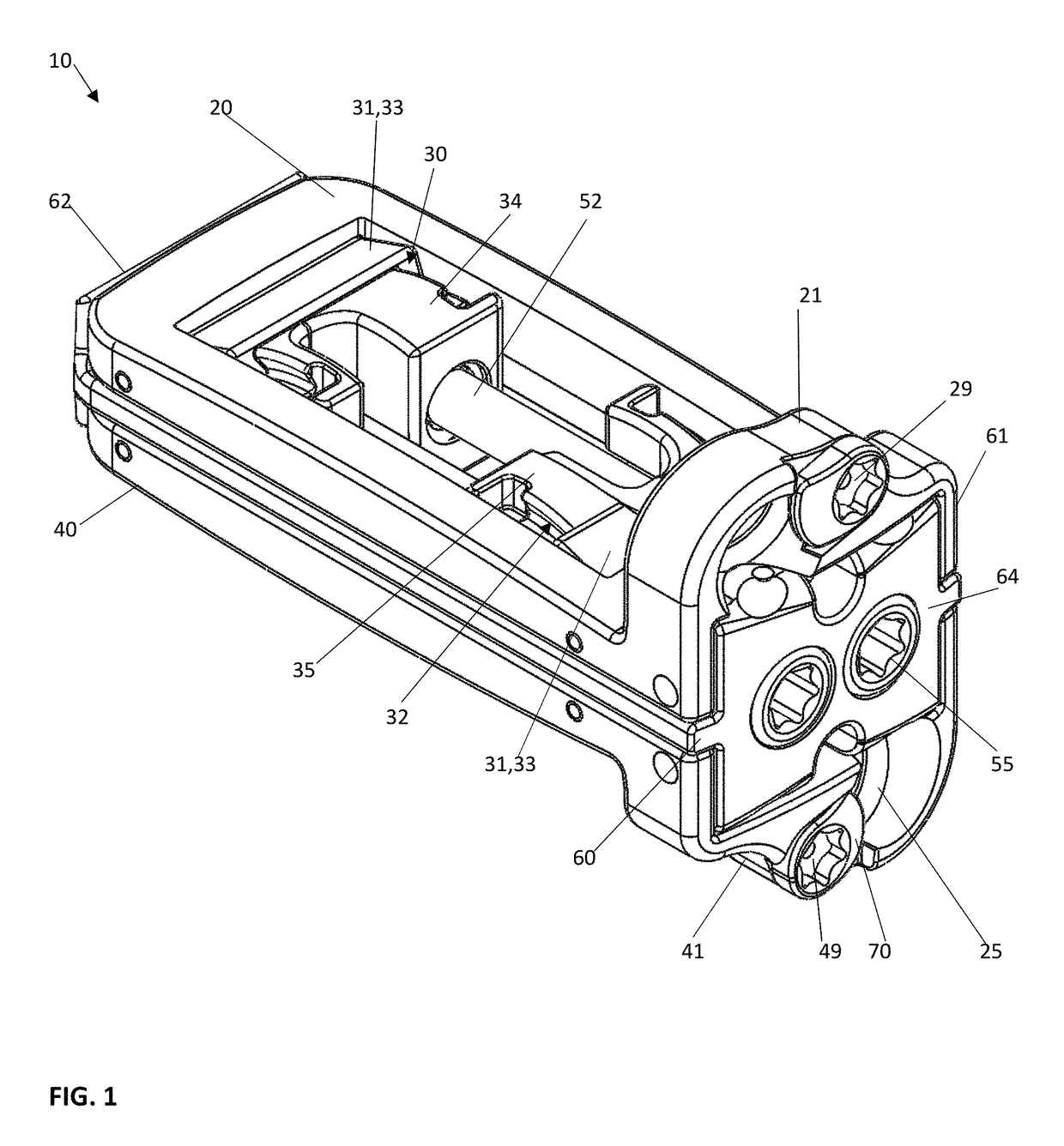
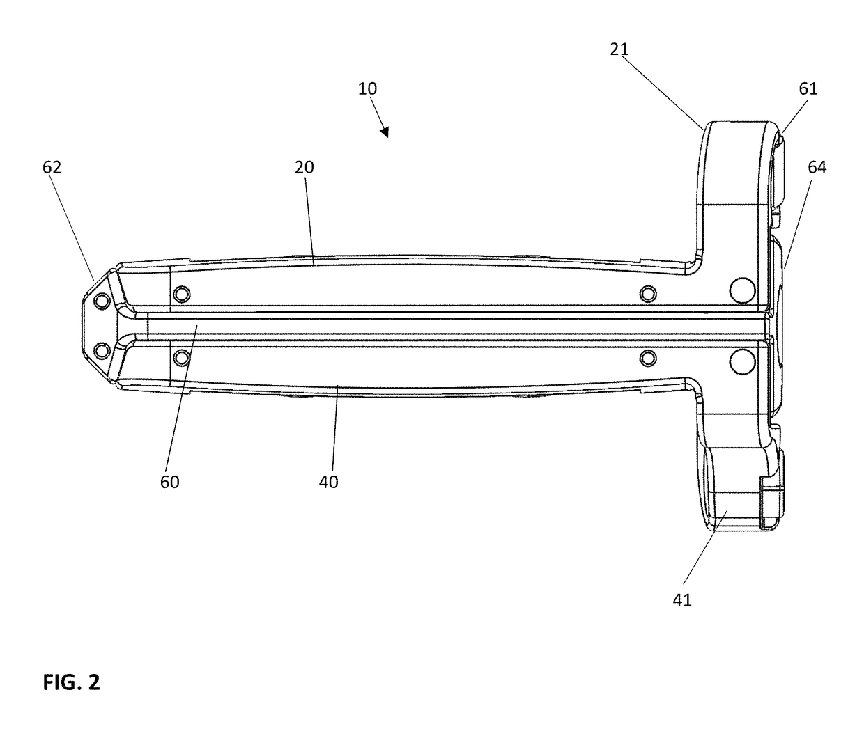
[0068]The intervertebral implant device with independent distal-proximal expansion of the present invention, hereinafter described as an expandable interbody fusion implant device 10, has a frame 60, two ramp assemblies, 30, 32 and two overlying base plates 20, 40 driven by two independent drive shafts 50, 52; as illustrated in FIG. 1.

[0069]With reference to FIGS. 1 and 2, the device 10 shows the frame 60 having a distal end 62 and a proximal end 61. The two ramp assemblies 30, 32 include a distal translating ramp 34 and a proximal translating ramp 35 respectively, and further have a first pivoting hinged ramp 31 and a second pivoting hinged ramp 33. The two overlying base plates 20, 40 are disposed between the distal end 62 and the proximal end 61. The first base plate 20 overlies the second base plate 40. Each base plate 20, 40 is hinged to a distal ramp assembly 30 and the proximal ramp assembly 32 at an end of one of the said pivoting hinged ramps of each ramp assembly. The two ...


PUM


Abstract

An expandable interbody fusion implant device has a frame, two ramp assemblies and two overlying base plates driven by two independent drive shafts. The two ramp assemblies include a distal ramp assembly and a proximal ramp assembly. Each ramp assembly has a translating ramp, a first pivoting hinged ramp and a second pivoting hinged ramp. The two overlying base plates include a first base plate overlying a second base plate. Each base plate is hinged to the distal ramp assembly and the proximal ramp assembly at an end of one of said pivoting hinged ramps of each ramp assembly. The two independently driven drive shafts include a first drive shaft for translating the distal ramp assembly and a second drive shaft for translating the proximal ramp assembly to independently expand the implant proximally or distally or both.

Description

TECHNICAL FIELD[0001]The present disclosure relates to an expandable interbody fusion implant device for implantation between vertebral bodies.BACKGROUND OF THE INVENTION[0002]Spinal stabilization can be achieved by providing an interbody implant. Some of these implants are bone, PEEK, solid titanium or similar non-bone implant material and some are hollow implants that provide for inclusion of a bone graft or other suitable material to facilitate bony union of the vertebrae.[0003]Interbody implants can be inserted into the disc space through an anterior, posterior or lateral approach. In some systems, the implants are inserted into a bore formed between adjacent vertebral bodies in the cortical endplates and can extend into the cancellous bone deep to the cortical endplates. Implant size is typically selected such that the implants force the vertebrae apart to cause tensing of the vertebral annulus and other soft tissue structures surrounding the joint space. Tensing the soft tissu...

Claims


Application Information

Patent Timeline
Patent Type & Authority Patents(United States)
IPC IPC(8): A61F2/44A61F2/30
CPCA61F2/447A61F2002/30476A61F2002/30579A61F2002/4475A61F2002/30387A61F2002/30556A61F2002/30266A61F2220/0008A61F2002/30405A61F2002/30507A61F2002/30515A61F2002/30538A61F2002/30578A61F2002/30593
Inventor DAFFINSON, BRIONHOWELL, AUSTINTHORNBURG, CHASE
Owner SPINAL ELEMENTS INC
Why Eureka
Try Eureka