Electrostatic coalescer and method for electrostatic coalescence

a coalescer and electrostatic technology, applied in electrochemical methods, water/sewage treatment, separation processes, etc., can solve problems such as heavy vessels and turbulence, and achieve the effects of reducing turbulence, improving coalescing performance, and improving coalescing

Active Publication Date: 2017-09-05
SULZER MANAGEMENT AG
View PDF14 Cites 0 Cited by
  • Summary
  • Abstract
  • Description
  • Claims
  • Application Information

AI Technical Summary

Benefits of technology

[0007]The present invention provides a device for electrostatic coalescence of liquid particles in a flowing fluid mixture, of the type according the preamble that also comprises a least one arrangement with flow guide vanes arranged in the tube, positioned in between the opened infeed side and an opposite opened outfeed side, for forcing the movement to the fluid mixture flowing through the tube, possibly with imparting a rotation to it. Different from the teachings according the prior art wherein a mere linear flow of the mixture in the vicinity of the electrodes is required the arrangement with flow guide vanes can force the movement of the fluid in the vicinity of the electrodes such that it either provides a rotating flow or that it reduces the turbulence. This guidance of the mixture, that leads away from the existing coalescers of this type, results in the ability of an electrostatic coalescer according the present invention to provide a better coalescing performance than a prior art electrostatic coalescer. The arrangement with flow guide vanes may for instance be implemented as a swirl element. Due to the turbulence the chance for contact / meeting of liquid particles to coalesce with other liquid particles to coalesce increases thus the coalescing effect may be enhanced at least as the turbulence is not, at least not in a serious rate, breaking up already coalesced particles. The arrangement with flow guide vanes can reduce the turbulence effects such that breaking up will not occur or it can generate centrifugal forces, acting along the axis of the pipe on the polarized liquid particles to coalesce (droplets). These particles will start to slip with the continuous phase with the slip velocity depending on the particle size. The differences in slip velocities for different sized particles will further support (increase) the coalescence in addition to coalescence due to any existing turbulent fluctuations. An option is to couple two or more coalescing devices according the present invention in line, as to coalesce the mixture subsequently plural times. The coalescence by means of electrostatics supported with induced swirl is preferably conducted on viscous liquid flow holding no gas or only low levels of gas.

Problems solved by technology

High viscosity crudes and heavy crude oils typically require long residence times for adequate liquid-liquid separation even with electrostatics in combination with high operating temperatures, thus resulting in a bulky and heavy vessel.

Method used


Image

  • Electrostatic coalescer and method for electrostatic coalescence
  • Electrostatic coalescer and method for electrostatic coalescence
  • Electrostatic coalescer and method for electrostatic coalescence

Examples


Embodiment Construction

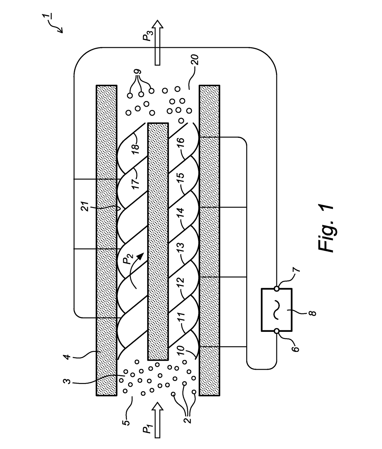
[0028]FIG. 1 shows an electrostatic coalescence device 1 for liquid particles 2 in a flowing fluid mixture 3 that a fed according to arrow P1 to a tube 4 having a feed opening 5. In the tube 4 helical blades 10-18 are arranged that impart a rotational movement according arrow P2 to the fluid mixture 3. The fluid mixture 3 that is fed (P1) to the coalescence device 1 comprises small relative liquid particles 2 that have a different composition compared to the main component of the fluid mixture 3, for instance water particles 2 in an oil flow. The water particles 2 (e.g. an emulsion of oil and water) are randomly distributed in the mixture 3 while entering the tube 4 at the feed opening 5. The helical blades 10-18 not only impart a rotational movement to the fluid mixture 3, the helical blades 10-18 are also providing an electric field to act on the mixture 3. The helical blades 10-18 are alternately electrically connected to the poles 6, 7 of an electric power source 8, so the helic...


PUM

PropertyMeasurementUnit
lengthaaaaaaaaaa
diameteraaaaaaaaaa
alternating currentaaaaaaaaaa

Abstract

The invention relates to a device for electrostatic coalescence of liquid particles in a flowing fluid mixture, comprising: a tube having an feed opening located at the front side of the tube and a discharge opening located on the opposite side of the tube and a least one arrangement with flow guide vanes arranged in the tube, positioned in between the opened infeed side and an opposite opened outfeed side, for reducing the turbulence or for imparting a rotating movement to the fluid mixture flowing through the tube. The invention also relates to a method for electrostatic coalescence of liquid particles in a flowing fluid mixture.

Description

CROSS-REFERENCE TO RELATED APPLICATIONS[0001]This application is the United States national phase of International Application No. PCT / NL2013 / 050001 filed Jan. 2, 2013, and claims priority to Netherlands Patent Application No. 2008071 filed Jan. 2, 2012, the disclosures of which are hereby incorporated in their entirety by reference.BACKGROUND OF THE INVENTION[0002]Field of the Invention[0003]The invention relates to a device for electrostatic coalescence of liquid particles in a flowing fluid mixture, especially for coalescence of water in an flowing water / oil fluid mixture, comprising: a tube having a feed opening located at the front side of the tube and a discharge opening located on the opposite side of the tube; power means for providing a current; and at least two electrodes located inside the tube electrically connected to the power means. The invention also relates to a method for electrostatic coalescence of liquid particles in a flowing fluid mixture, especially for coale...

Claims


Application Information

Patent Timeline
Patent Type & Authority Patents(United States)
IPC IPC(8): B01D17/06B03C11/00C02F1/46C02F1/461C02F1/48B01D17/04C02F101/32
CPCB03C11/00B01D17/045B01D17/06C02F1/46104C02F1/48B03C2201/02C02F2101/325C08F10/00
Inventor TIENHAARAA, MIKA KRISTIAN SULEVILAMMERS, FREDERIK ALBERT
Owner SULZER MANAGEMENT AG
Why Eureka
Try Eureka