
Power gate placement techniques in three-dimensional (3D) integrated circuits (ICs) (3DICs)

a technology of integrated circuits and power gates, applied in the field of integrated circuits, can solve the problems of increasing versatility, increasing the drain on the batteries used to power mobile computing devices, and imposing the penalty of so as to minimize the distance between the voltage source and and the power loss of routing elements therebetween, the effect of minimizing the distance between the power gating circuit and downstream elements

Active Publication Date: 2017-09-05
QUALCOMM INC
View PDF12 Cites 22 Cited by
  • Summary
  • Abstract
  • Description
  • Claims
  • Application Information

AI Technical Summary

Benefits of technology

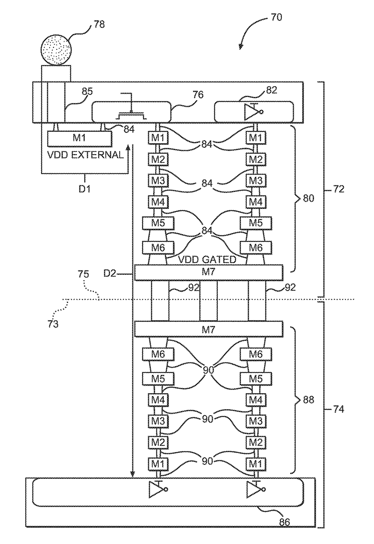
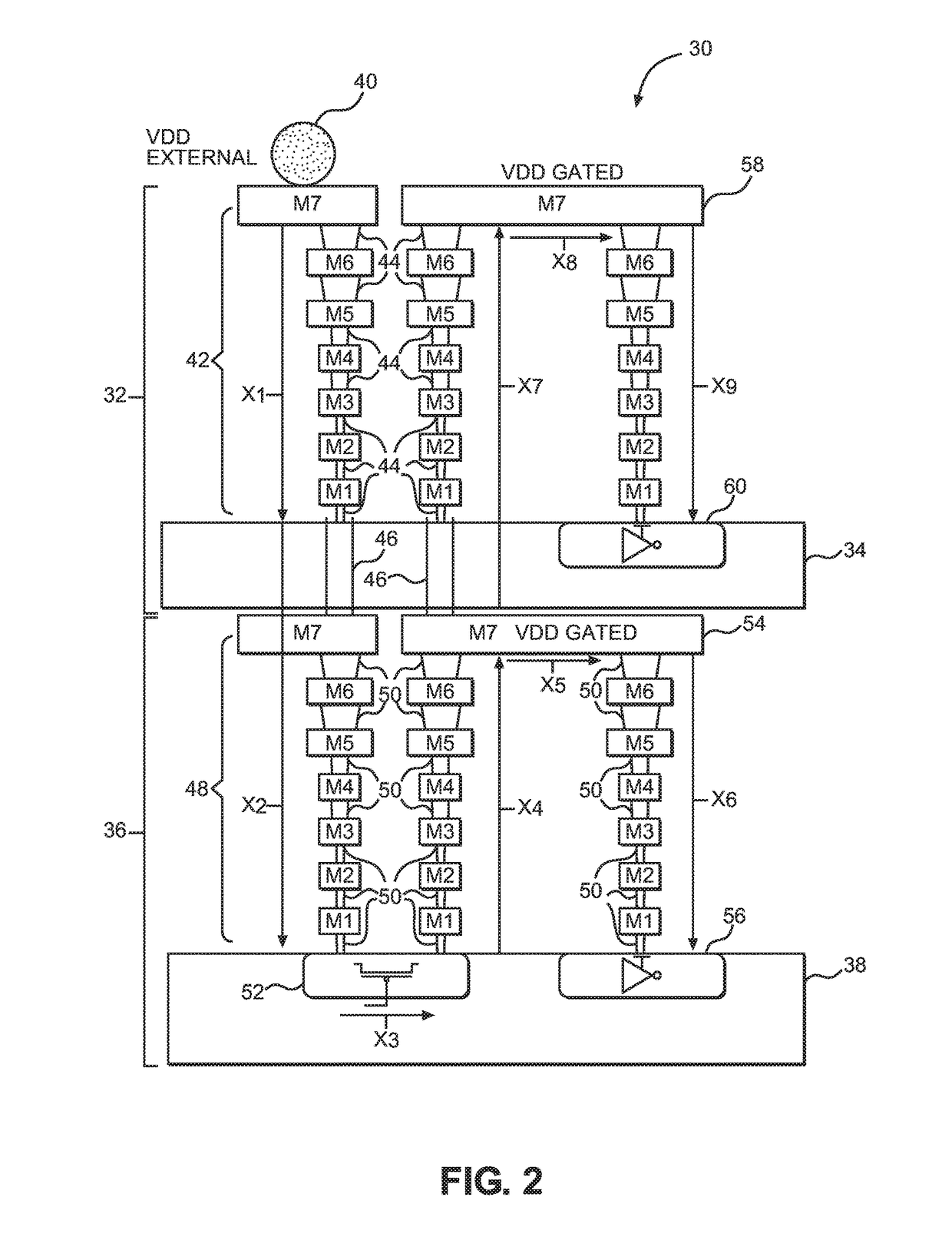
This patent describes a technique for placing power gating circuits in three-dimensional ICs (3DICs). The technique involves consolidating power gating circuits into a single tier within the 3DIC, allowing for closer proximity to the voltage source and minimizing power loss from routing elements. By doing this, the technique achieves improved performance and power efficiency in the 3DIC. The patent also includes a method for designing a monolithic 3DIC, which involves placing logic circuits and power gating circuits on separate tiers and arranging them in a face-to-face arrangement to minimize voltage drop between the voltage source and the power gating circuits.

Problems solved by technology

While the increase in functionality has increased the versatility of the devices, the increase in versatility also increases the drain on the batteries used to power such mobile computing device.
Even in sleep mode, some elements within an integrated circuit (IC) may continue to consume power because of stand-by or leakage current of transistors within the IC.
While power gating circuits may be effective at limiting power consumption within an IC, power gating circuits involve a variety of engineering tradeoffs.
One such tradeoff is the area penalty imposed by the power gating circuit.
An issue conjoined with the area penalty is how placement of the power gating circuit within the IC will impact routing of interconnections between other elements within the IC.

Method used


Image

  • Power gate placement techniques in three-dimensional (3D) integrated circuits (ICs) (3DICs)
  • Power gate placement techniques in three-dimensional (3D) integrated circuits (ICs) (3DICs)
  • Power gate placement techniques in three-dimensional (3D) integrated circuits (ICs) (3DICs)

Examples


Embodiment Construction

[0020]With reference now to the drawing figures, several exemplary aspects of the present disclosure are described. The word “exemplary” is used herein to mean “serving as an example, instance, or illustration.” Any aspect described herein as “exemplary” is not necessarily to be construed as preferred or advantageous over other aspects.

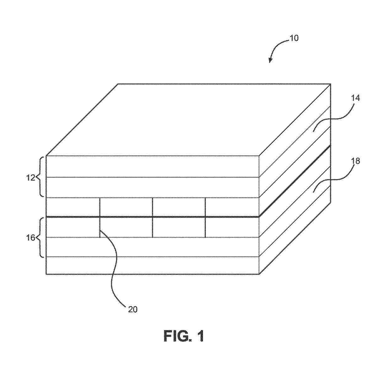
[0021]Aspects disclosed in the detailed description include power gate placement techniques in three-dimensional (3D) integrated circuits (ICs) (3DICs). In particular, exemplary aspects of the present disclosure contemplate consolidating power gating circuits or cells into a single tier within a 3DIC. Still further, in an exemplary aspect, the power gating circuits are consolidated in a tier closest to a voltage source. While it is possible to merely be near the voltage source, maximum benefit is achieved by being in the closest tier. This closest tier may include a backside metal layer that allows a distance between the voltage source and the power g...


PUM


Abstract

Power gate placement techniques in three-dimensional (3D) integrated circuits (ICs) (3DICs) are disclosed. Exemplary aspects of the present disclosure contemplate consolidating power gating circuits or cells into a single tier within a 3DIC. Still further, the power gating circuits are consolidated in a tier closest to a voltage source. This closest tier may include a backside metal layer that allows a distance between the voltage source and the power gating circuits to be minimized. By minimizing the distance between the voltage source and the power gating circuits, power loss from routing elements therebetween is minimized. Further, by consolidating the power gating circuits in a single tier, routing distances between the power gating circuits and downstream elements may be minimized and power loss from those routing elements are minimized. Other advantages are likewise realized by placement of the power gating circuits according to exemplary aspects of the present disclosure.

Description

BACKGROUND[0001]I. Field of the Disclosure[0002]The technology of the disclosure relates generally to integrated circuits (ICs) and, more particularly, to placement of power gates in three-dimensional (3D) integrated circuits (ICs) (3DICs).[0003]II. Background[0004]Computing devices have become prevalent in modern society. While desktop computing remains widespread, recent years have seen an increase in the number of mobile computing devices. The increase in the number of mobile computing devices is driven in part by their relative affordability and the ever increasing functionality provided on such devices. While the increase in functionality has increased the versatility of the devices, the increase in versatility also increases the drain on the batteries used to power such mobile computing device. In an effort to extend battery life, various power-saving techniques have been implemented, such as putting elements in a sleep mode when such elements are not in use.[0005]Even in slee...

Claims


Application Information

Patent Timeline
Patent Type & Authority Patents(United States)
IPC IPC(8): H01L25/065H01L27/06H01L23/48G06F17/50H01L23/528H01L23/00H01L23/522
CPCH01L25/0657G06F17/5072H01L23/481H01L23/528H01L23/5226H01L24/13H01L27/0688H01L2224/13014H01L2224/13016H01L2224/13023H01L2224/13025H01L2225/06541H01L2924/13091H01L2924/141H01L2924/1431H01L2924/1434H01L2924/14335H01L23/5283H01L23/5286H01L25/16H01L2225/06548H01L2924/00014H01L2224/1411H01L24/14G06F30/398G06F30/392G06F2119/06H01L2224/13099H01L2224/16225
Inventor XIE, JINGSAMADI, KAMBIZKAMAL, PRATYUSHDU, YANGJAFFARI, JAVID
Owner QUALCOMM INC
Learn More