
Closed loop control

a closed loop and control technology, applied in the field of assemblies, can solve the problems of extra hard and software, expensive solutions,

Inactive Publication Date: 2017-09-12
APPLIED MATERIALS INC
View PDF4 Cites 4 Cited by
  • Summary
  • Abstract
  • Description
  • Claims
  • Application Information

AI Technical Summary

Benefits of technology

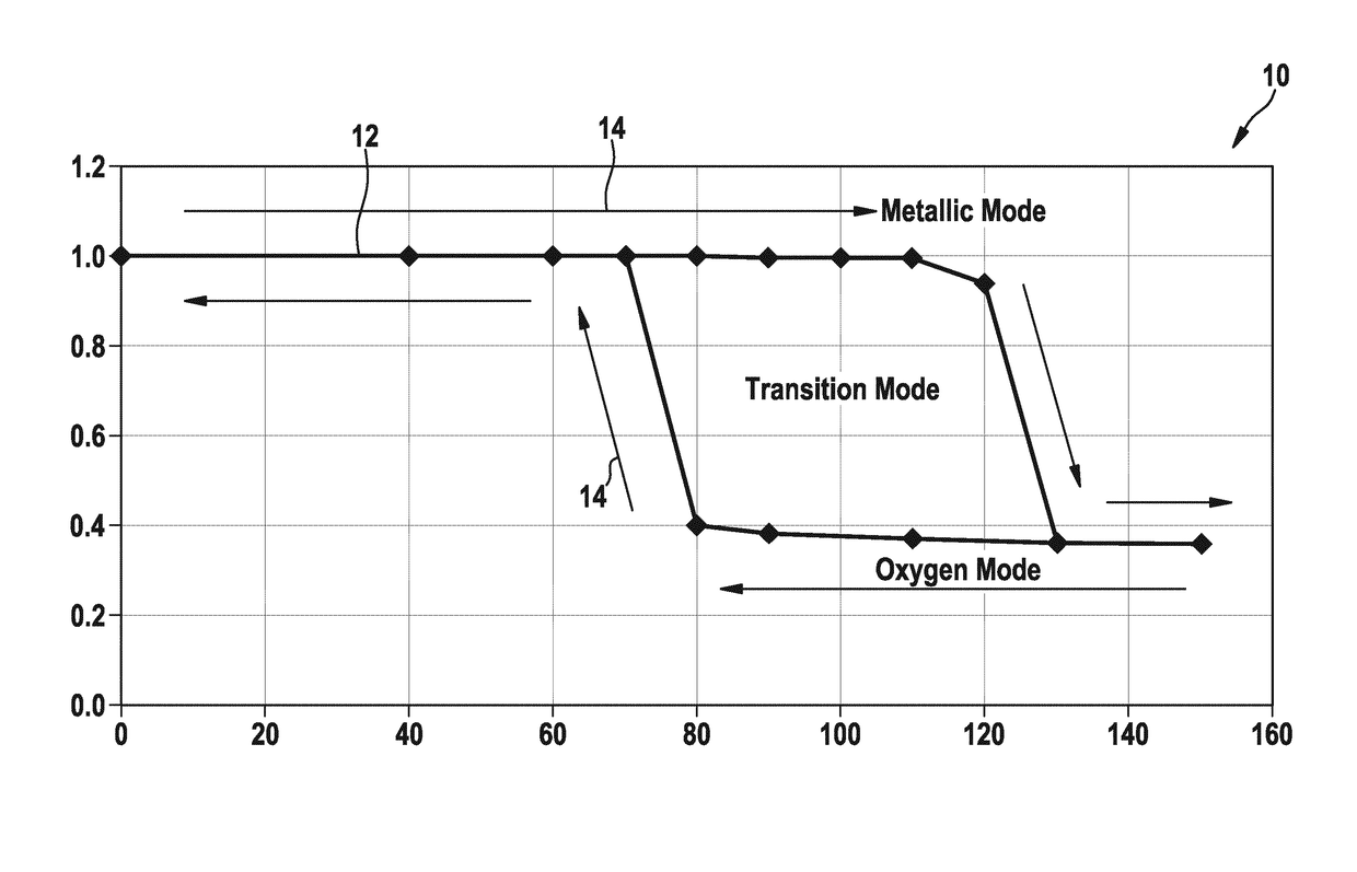
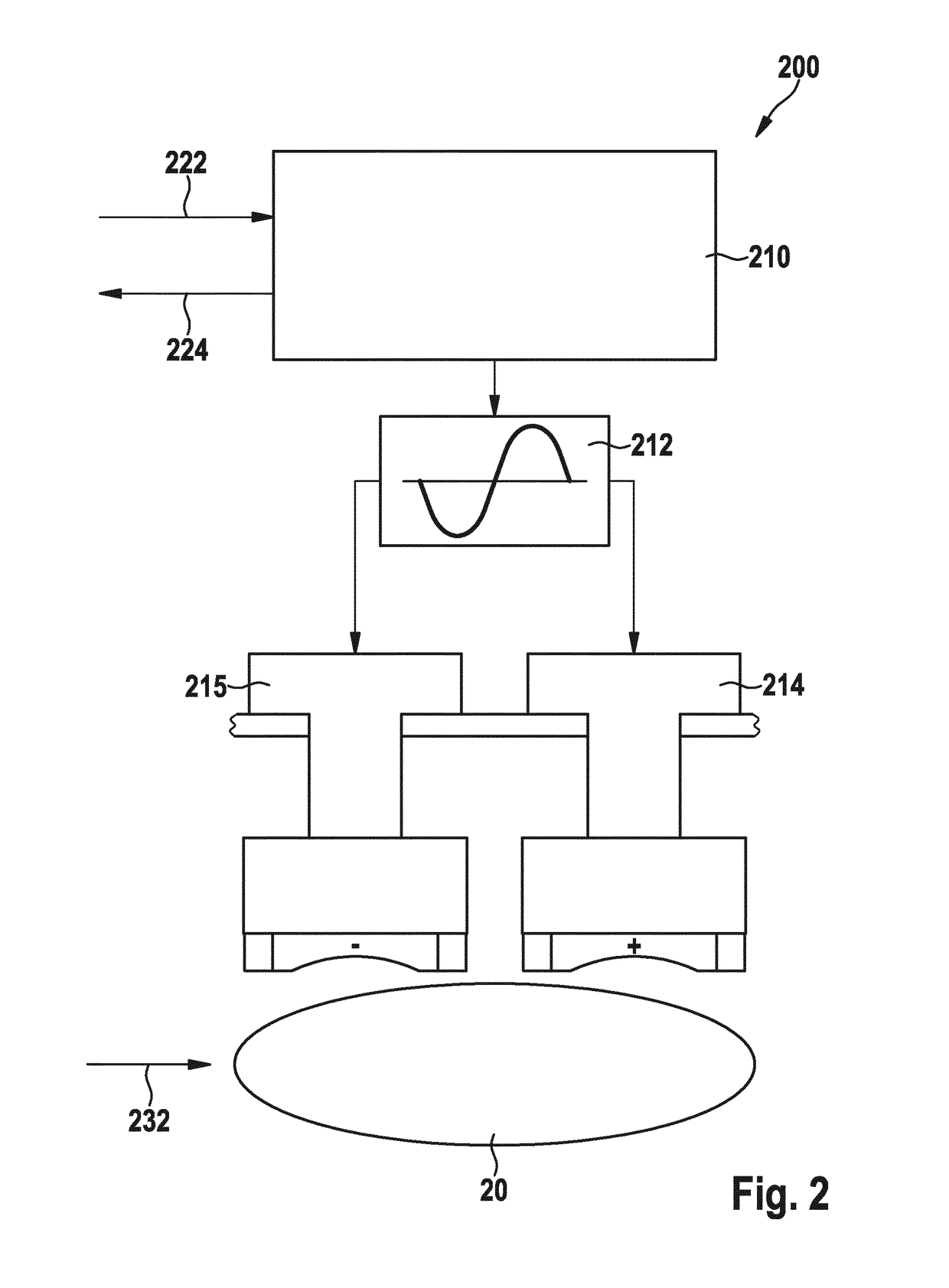
The present invention provides a method, a closed loop control assembly, and a deposition apparatus for reactive deposition of a layer on a substrate. The invention allows for controlled deposition of the layer based on the power value provided to the substrate during the deposition process. The technical effects achieved by the invention include improved quality and consistency of the deposition process, reduced production costs, and improved production efficiency.

Problems solved by technology

This needs extra hard- and software and is therefore an expensive solution.

Method used


Image

  • Closed loop control
  • Closed loop control
  • Closed loop control

Examples


Embodiment Construction

[0017]Reference will now be made in detail to the various embodiments of the invention, one or more examples of which are illustrated in the figures. Within the following description of the drawings, the same reference numbers refer to same components. Generally, only the differences with respect to individual embodiments are described. Each example is provided by way of explanation of the invention and is not meant as a limitation of the invention. Further, features illustrated or described as part of one embodiment can be used on or in conjunction with other embodiments to yield yet a further embodiment. It is intended that the description includes such modifications and variations.

[0018]Embodiments described herein refer inter alia to a substrate processing system adapted for processing a flexible substrate such as a web for packaging, for flexible photovoltaic devices or other applications. In particular, the substrate processing system is adapted for a continuous processing of ...


PUM

PropertyMeasurementUnit
oscillation frequencyaaaaaaaaaa
oscillating frequencyaaaaaaaaaa
poweraaaaaaaaaa

Abstract

A method of controlling a reactive deposition process and a corresponding assembly and / or apparatus are described. The method includes providing power to a cathode with a power supply, providing a voltage set point to the power supply, receiving a power value correlating the power provided to the cathode, and controlling a flow of a process gas in dependence of the power value to provide a closed loop control for the power value.

Description

TECHNICAL FIELD OF THE INVENTION[0001]Embodiments of the present invention relate to assemblies for control of reactive deposition processes, apparatuses including such assemblies and methods of controlling reactive deposition processes. Embodiments of the present invention particularly relate to a closed loop controlled assembly for a reactive deposition process, a deposition apparatus including a closed loop controlled apparatus for a reactive deposition process and a method of controlling a reactive deposition process.BACKGROUND OF THE INVENTION[0002]In many applications, it is necessary to deposit thin layers on a substrate, e.g. a flexible substrate. Typically, the flexible substrates are coated in different chambers of a flexible substrate coating apparatus. Further, a stock of a flexible substrate, for example, a roll of a flexible substrate, may be disposed in one chamber of the substrate coating apparatus. Typically, the flexible substrates are coated in a vacuum, using a v...

Claims


Application Information

Patent Timeline
Patent Type & Authority Patents(United States)
IPC IPC(8): C23C14/34C23C14/56H01J37/32C23C14/00H01J37/34
CPCC23C14/0042C23C14/0036C23C14/0094C23C14/56C23C14/562H01J37/32935H01J37/34H01J2237/332
Inventor DEPPISCH, THOMASHELLE, FRANZ-JOSEFENGLERT, MANFREDHERMANNS, UWE
Owner APPLIED MATERIALS INC
Learn More