Heater control apparatus for gas sensor

a gas sensor and control apparatus technology, applied in the field of heater control apparatus, to achieve the effect of accurately obtaining the average of element resistance, accurate average of element resistance values, and simplified processing

Active Publication Date: 2017-09-19
NGK SPARK PLUG CO LTD
View PDF5 Cites 0 Cited by
  • Summary
  • Abstract
  • Description
  • Claims
  • Application Information

AI Technical Summary

Benefits of technology

[0009]The present invention has been made in order to solve the above-described problems, and an object thereof is to provide a heater control apparatus for a gas sensor which can obtain an element resistance while mitigating the influence of noise without changing the timing of detecting the element resistance or the timing of on / off switching by PWM control, and which can control energization of a heater based on the element resistance.
[0011]The heater control apparatus for a gas sensor according to the above embodiment can obtain the average of element resistance values used for controlling energization of the heater while excluding an element resistance value(s) which may be influenced by noise or the like. Noise or the like is apt to be generated when energization of the heater is started or stopped. The heater control apparatus can obtain the average of element resistance values accurately, even when the heater control apparatus obtains an element resistance value(s) influenced by noise. Therefore, it is unnecessary to configure the heater control apparatus to obtain the element resistance values while avoiding the timings at which energization of the heater is started and stopped. Therefore, the processing can be simplified. Also, since the heater control apparatus need not detect the timings at which the energization of the heater is started and stopped, the heater control apparatus is always available to perform the operation of obtaining the element resistance.
[0012]Also, in the present mode, by excluding element resistance value(s) which do not fall within a range (window) set based on the average (reference) or excluding two element resistance values whose difference from the average are the largest and the second largest, the heater control apparatus can easily exclude an element resistance value(s) which may have been affected by noise or the like and can obtain the average of the element resistances accurately in each of the above-described cases. By controlling energization of the heater using the accurate average of the element resistance values, the heater control apparatus can heat the gas detection element at a proper temperature, and, consequently, can accurately detect the concentration of a specific gas.

Problems solved by technology

If the timing of on / off switching (starting / stopping) of the energization of the heater by the PWM control overlaps with the timing (period) of detection of the element resistance, a signal representing the detected element resistance may contain noise.

Method used


Image

  • Heater control apparatus for gas sensor
  • Heater control apparatus for gas sensor
  • Heater control apparatus for gas sensor

Examples


first embodiment

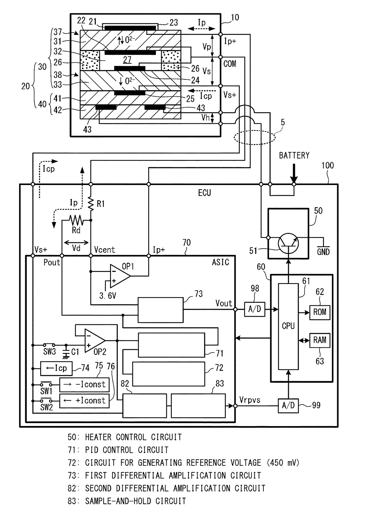
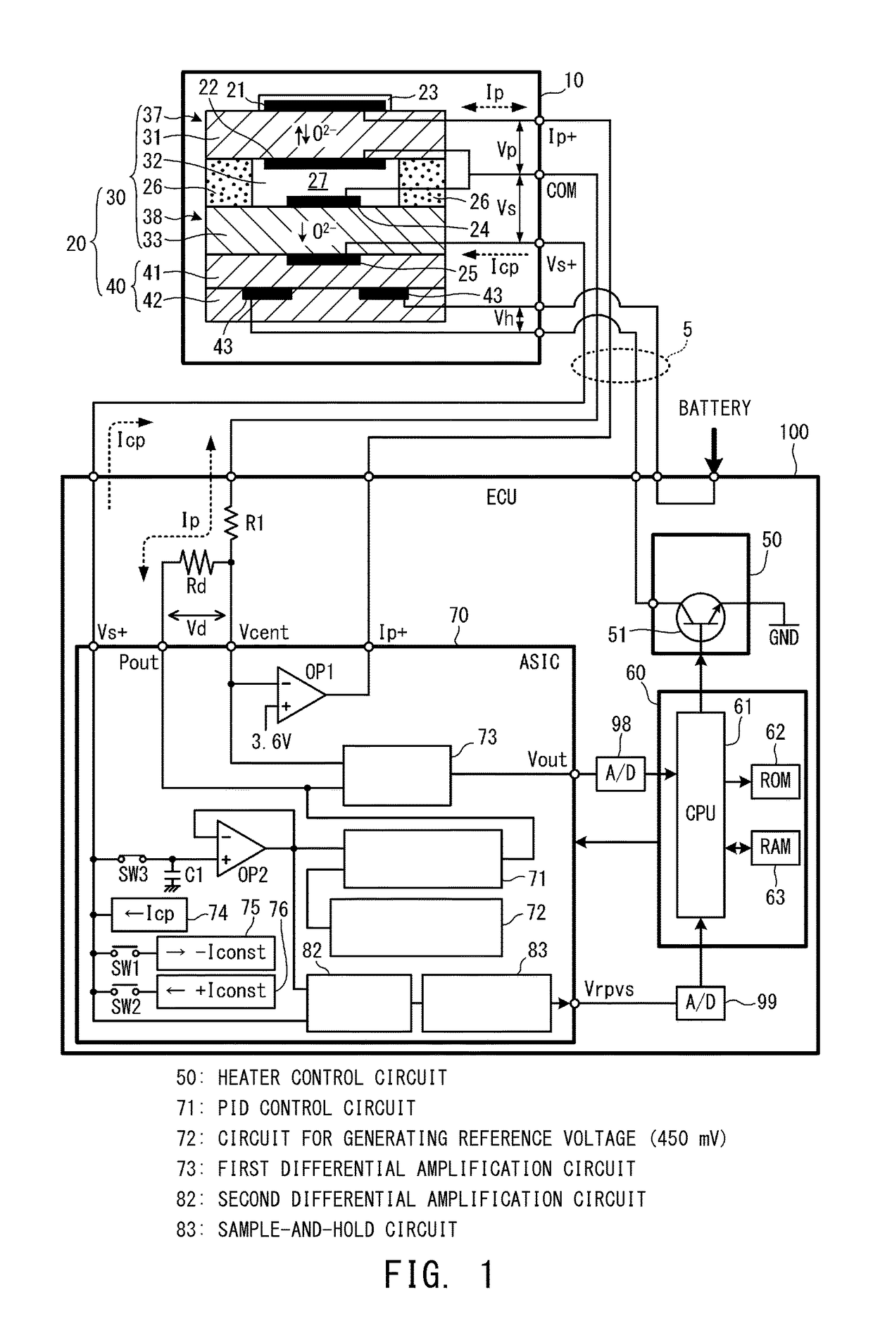
[0027]In a first embodiment, the gas sensor is a full-range air-fuel-ratio sensor 10, and the heater control apparatus is an electronic control apparatus (ECU) 100 of an automobile. The configurations of the full-range air-fuel-ratio sensor 10 and the ECU 100 will be described with reference to FIG. 1. Notably, since the full-range air-fuel-ratio sensor 10 has a known configuration, the details of its structure, etc., will not be described, and its schematic configuration will be described below.

[0028]The full-range air-fuel-ratio sensor 10 shown in FIG. 1 is a sensor which is attached to an exhaust passage (not shown) of an engine of an automobile and which detects the air-fuel ratio of exhaust gas flowing through the exhaust passage based on the oxygen concentration of the exhaust gas. The full-range air-fuel-ratio sensor 10 has an unillustrated housing and a narrow, elongated plate-shaped sensor element 20 held within the housing. The full-range air-fuel-ratio sensor 10 has a plu...

second embodiment

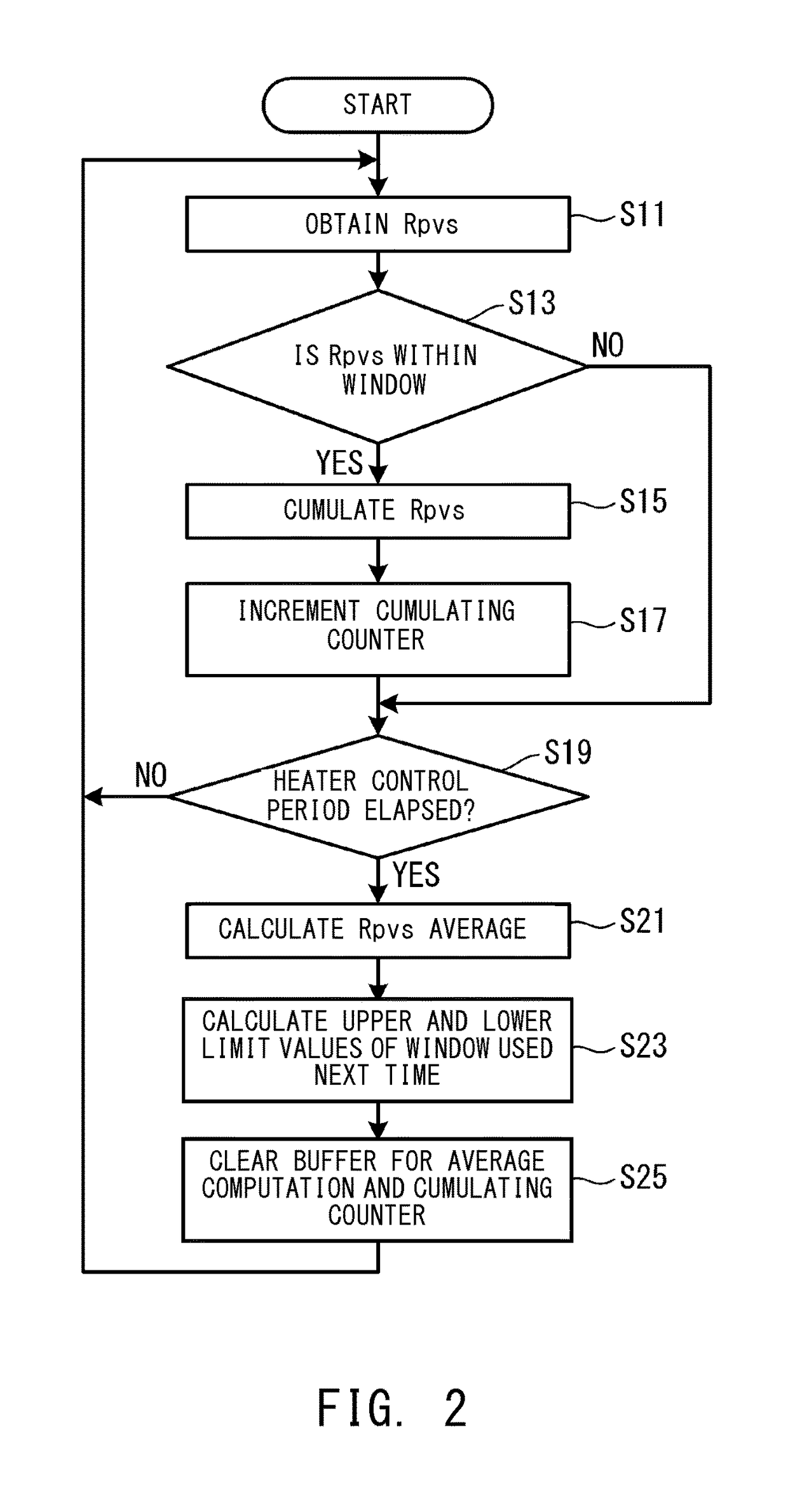
[0061]In the second embodiment, the CPU 61 performs the Rpvs computation processing to thereby obtain the element resistance (Rpvs) of the Vs cell 38 a plurality of times during each period (PWM control period) within which the heater 40 is energized one time. The CPU 61 calculates the average of the Rpvs values (the Rpvs average) for this PWM control period after excluding two Rpvs values whose differences (deviations) from the Rpvs average obtained in the last control period are the largest and the second largest and on which noise may be superimposed. Noise is likely to be generated when energization of the heater 40 is started or stopped, and there is a possibility that noise is superimposed on two of a plurality of Rpvs values obtained during a single PWM control period. In some cases, both the Rpvs value on which noise generated as a result of starting energization of the heater 40 has been superimposed and the Rpvs value on which noise generated as a result of stopping energi...


PUM

PropertyMeasurementUnit
voltageaaaaaaaaaa
reference voltageaaaaaaaaaa
temperaturesaaaaaaaaaa

Abstract

In a heather control apparatus for a gas sensor, a CPU obtains upper and lower limit values by adding a predetermined value to and subtracting the predetermined value from an Rpvs average obtained in a last heater energization period (or to an Rpvs value obtained for the first time), and sets a window W1. The CPU obtains a plurality of Rpvs values [P2] to [P11], and obtains an Rpvs average A1 while excluding Rpvs values [P5], [P6], and [P9] which do not fall within the window W1 (not less than the lower limit value and not greater than the upper limit value). The CPU obtains the upper and lower limit values by adding the predetermined value to and subtracting the predetermined value from the Rpvs average A1, and sets a window W2 for the next heater energization period.

Description

BACKGROUND OF THE INVENTION[0001]1. Field of the Invention[0002]The present invention relates to a heater control apparatus for controlling energization of a heater which activates a gas detection element of a gas sensor.[0003]2. Description of the Related Art[0004]A gas sensor has been known which includes a gas detection element having at least one cell composed of a solid electrolyte member and a pair of electrodes, and which detects the concentration of a specific gas such as oxygen. When the temperature of the gas detection element rises, the gas detection element becomes active. Further, the solid electrolyte member exhibits good oxygen-ion conductivity, whereby detection of the concentration of the specific gas becomes possible. The gas detection element is heated by the heat of exhaust gas discharged from an internal combustion engine. Meanwhile, the gas sensor has a heater in order to activate the gas detection element quickly and secure stability of operation by maintainin...

Claims


Application Information

Patent Timeline
Patent Type & Authority Patents(United States)
IPC IPC(8): H05B1/02G01N27/407G01N27/406
CPCH05B1/0244G01N27/407G01N27/4067
Inventor YAZAWA, KATSUNORIUEMURA, TOMONORI
Owner NGK SPARK PLUG CO LTD
Why Eureka
Try Eureka