
Low headloss feed devices and control methods for tray-type vortex grit removal systems

a vortex grit and feed device technology, applied in the field of wastewater treatment, can solve the problems of accelerated wear, premature failure of components, interference with the performance of downstream machinery where the grit is present, etc., and achieve the effect of improving grit removal efficiency and reducing headloss

Active Publication Date: 2017-09-26
ENVIRODYNE SYST
View PDF8 Cites 2 Cited by
  • Summary
  • Abstract
  • Description
  • Claims
  • Application Information

AI Technical Summary

Benefits of technology

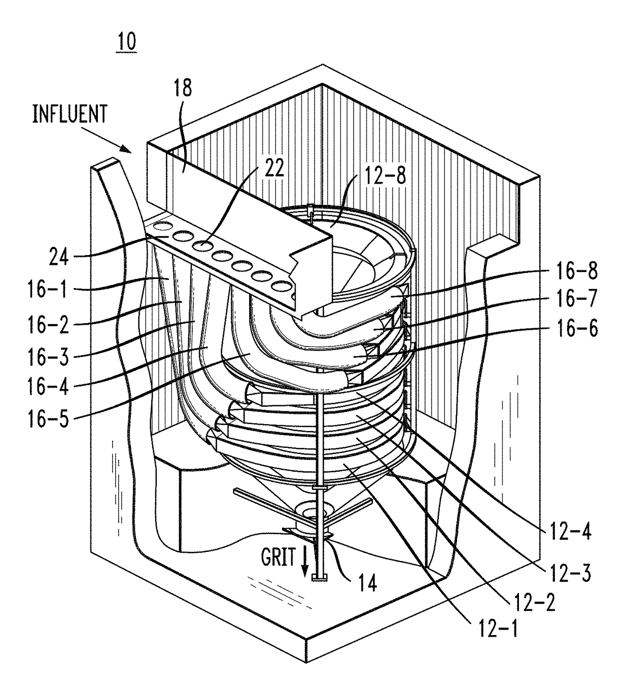
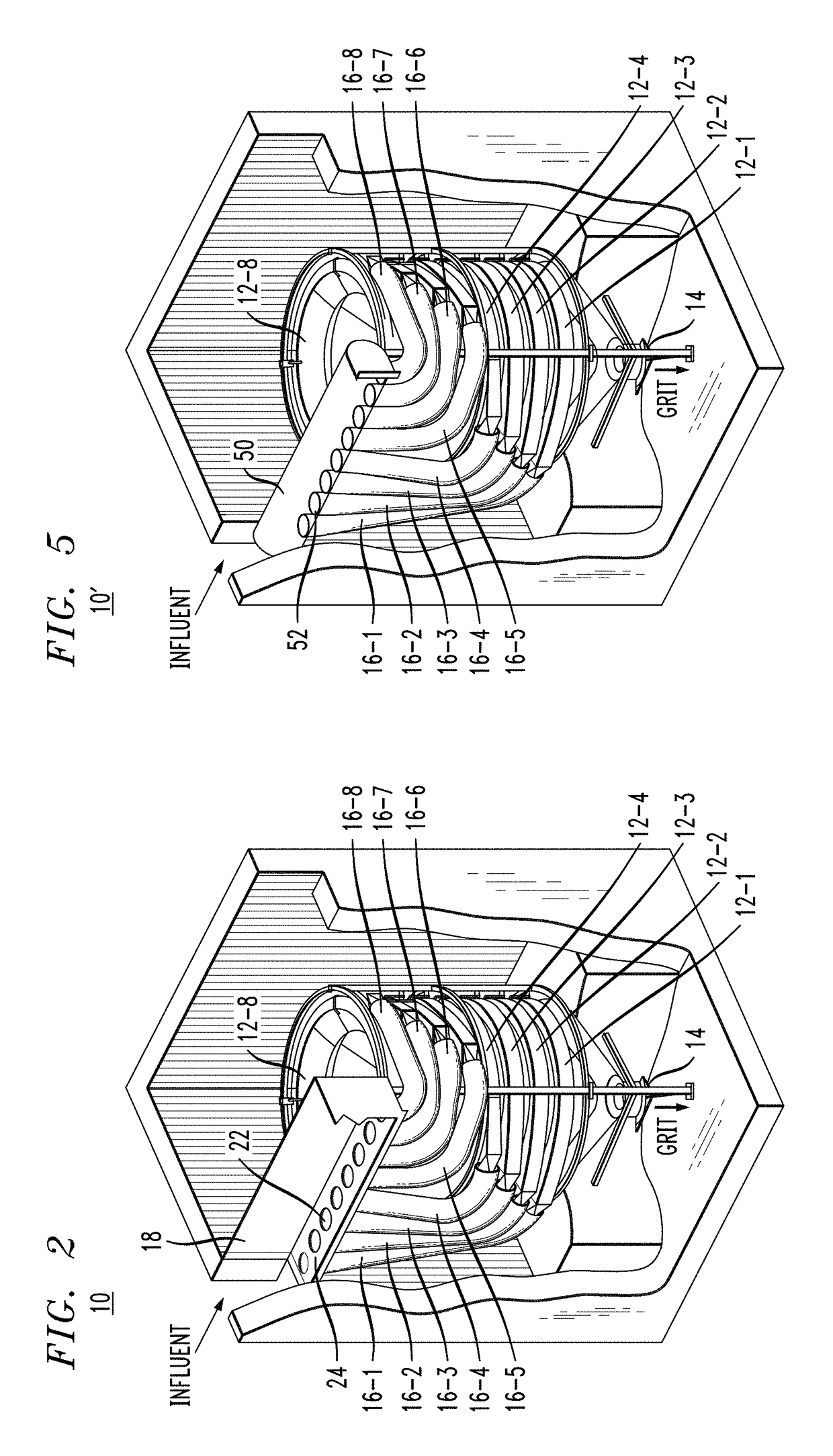
The present invention is a new invention that improves the removal of grit and reduces headloss in a system. It uses a horizontal inlet chute that allows for better control and even distribution of influent across all trays. The number of hoses can be easily changed as trays are added or removed. The invention also includes various gates, valves, plugs, and other devices to control the flow and improve performance. Overall, the invention provides a more efficient and effective way to remove grit and control the flow in a system.

Problems solved by technology

The grit takes the form of minute particles that, if not removed, interferes with the performance of downstream machinery where the grit may collect.
In particular, the grit may lead to premature failure of components, accelerated wear, etc.
While able to increase the number of trays used to remove grit, the pressure differential at the input to the various trays is problematic and results in non-uniform grit removal.
While the modified inlet duct geometry may reduce the overall headloss, the vertical arrangement of the inlet duct results in uneven path lengths between the entrance of the system and each tray, presenting a varying pressure differential to each tray.
As a result, short-circuiting of flow and grit loadings to each tray will occur.

Method used


Image

  • Low headloss feed devices and control methods for tray-type vortex grit removal systems
  • Low headloss feed devices and control methods for tray-type vortex grit removal systems
  • Low headloss feed devices and control methods for tray-type vortex grit removal systems

Examples


Embodiment Construction

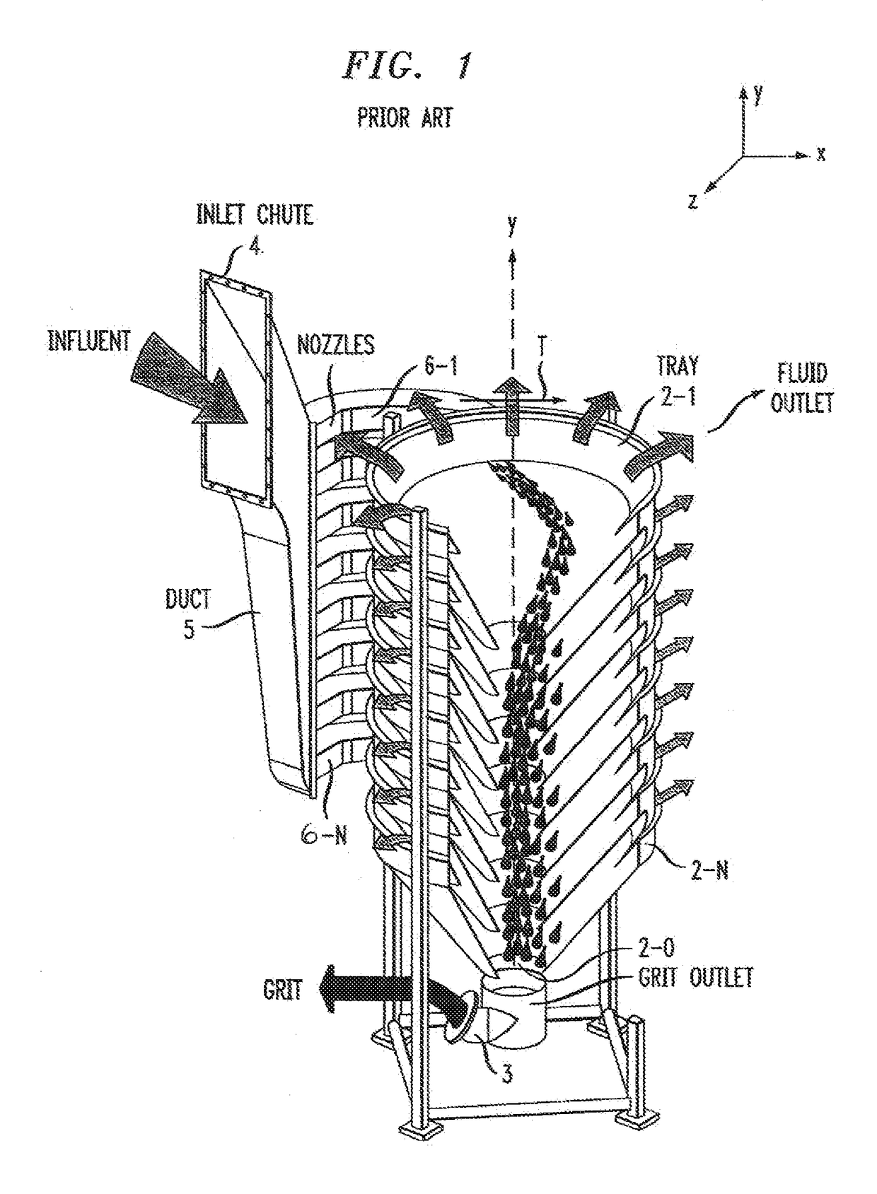
[0022]FIG. 1 illustrates a conventional, prior art grit removal system 1. A brief review of the operation of such a system is considered to be important to best understanding the subject matter of the present invention, as fully described hereinafter in association with FIGS. 2-10.

[0023]Grit removal system 1 is illustrated in a partially cut-away view in FIG. 1, allowing for the geometry of the stack of trays and movement of the grit to be easily shown. System 1 is typically configured to include a plurality of frusto-conical trays 2 that are stacked in the vertical direction. The vertical direction is indicated as the y-axis in FIG. 1, and may also be considered as the direction along which the grit will move (downward) and ultimately exit system 1 through a grit outlet 3.

[0024]In operation, wastewater (hereinafter referred to as “influent”) is introduced into system 1 through an inlet chute 4, where it fills a vertically-oriented inlet duct 5. In the particular configuration shown...


PUM

PropertyMeasurementUnit
sizeaaaaaaaaaa
sizeaaaaaaaaaa
lengthaaaaaaaaaa

Abstract

An inlet arrangement for a tray-based grit removal system utilizes a set of separate inlet hoses to connect the vertical stack of trays to a horizontally-disposed inlet chute, thus eliminating the inlet duct utilized in prior art configurations. Each hose is configured to have about the same length and diameter, providing an essentially uniform influent pressure at the input to each tray. The hoses are directly connected between the trays and the inlet chute, where each tray may be formed to include a hose coupler of the same diameter as the hose. The inlet chute may take the form of a trough or tube (or other suitable geometry), with the plurality of hoses all terminating along a common, horizontal output face of the chute.

Description

TECHNICAL FIELD[0001]The present invention relates to wastewater treatment and, more particularly, to an inlet configuration particularly designed to improve grit removal efficiency and reduce headloss in tray-type vortex grit removal systems.BACKGROUND OF THE INVENTION[0002]The need to remove grit from wastewater is a well-known concern. The grit takes the form of minute particles that, if not removed, interferes with the performance of downstream machinery where the grit may collect. In particular, the grit may lead to premature failure of components, accelerated wear, etc. The industry has used various arrangements over the years to remove as much grit as possible from wastewater at its initial introduction to a treatment facility. Depending on local conditions, the grit may vary in size (as well as composition), ranging from coarse grit on the order of about 300 microns down to fine grit typically on the order of about 100 microns.[0003]Of the various types of grit removal syste...

Claims


Application Information

Patent Timeline
Patent Type & Authority Patents(United States)
IPC IPC(8): B01D21/26B01D21/30C02F1/38B03B5/28B01D21/00B04C3/04B04C5/04B01D21/24
CPCB04C5/04B01D21/267C02F1/385B01D21/0051B01D21/2405B01D21/26B01D21/0024B03B5/28B01D21/2411B01D21/0045C02F2209/40C02F2301/026B01D21/2422E03F5/0403C02F1/006C02F2303/14C02F2303/24
Inventor SHEKER, ROBERT E.SHANAFELTER, ROYBUSHEY, ERIC ALAN
Owner ENVIRODYNE SYST
Learn More