Anaerobic jar mechanical sand discharging device

An anaerobic tank and mechanical technology, applied in the field of anaerobic tank, can solve the problems such as the inability of continuous operation of the sand discharge pipeline, the inability to empty and handle the sediment, and the limited stirring force, so as to improve the efficiency of sand removal, maintenance and repair. Small workload, eliminating the effect of dispersion and retention

Pending Publication Date: 2019-03-22
CHANGCHUN POWER GENERATION EQUIP PLANT
View PDF16 Cites 1 Cited by
  • Summary
  • Abstract
  • Description
  • Claims
  • Application Information

AI Technical Summary

Problems solved by technology

[0002] The biochemical treatment of pollutants such as domestic garbage, kitchen waste, and feces is mostly fermented by anaerobic tanks, and the waste is made into biogas and harmless organic fertilizers. The bottom of anaerobic tanks will accumulate sediment after long-term operation, but anaerobic The tank cannot be emptied to handle sediment, and it is often discharged when the equipment is in operation. The current main method of sand discharge is to discharge sand through the pipeline at the bottom of the anaerobic tank. Since the sand discharge pipeline cannot be continuously operated, it remains in the sand when the sand discharge pipeline is closed. The accumulation of sand and stones in the pipeline will form a blockage in the pipeline, and there must be a cleaning process when sand is discharged again
In addition, the sand and stones that sink to the bottom of the tank are mainly accumulated towards the sand discharge pipe interface through the inclination of the conical surface of the tank bottom and the stirring device. However, due to the large diameter of the anaerobic tank and the limited stirring force, the sand and stones are not easy to slide down on the bottom surface. the lowest point, so that this part of the sand remains in the tank

Method used


Image

  • Anaerobic jar mechanical sand discharging device
  • Anaerobic jar mechanical sand discharging device
  • Anaerobic jar mechanical sand discharging device

Examples


Embodiment Construction

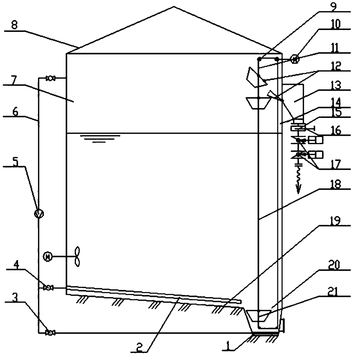
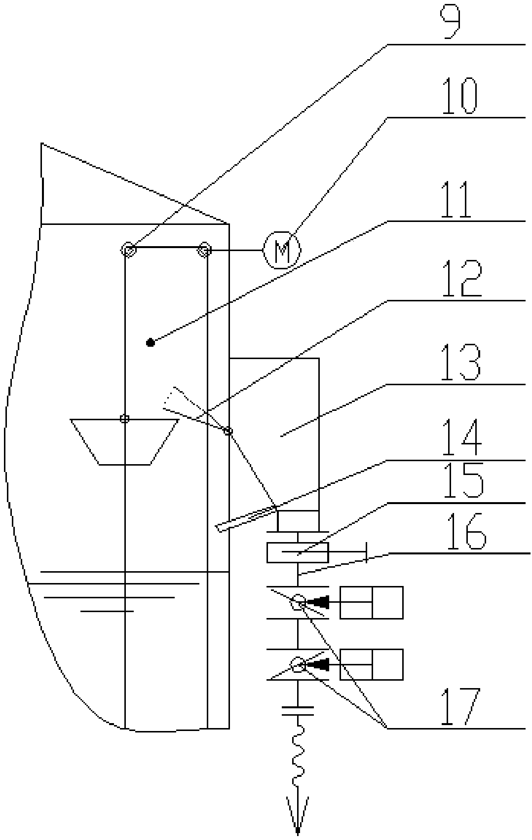
[0015] refer to figure 1 , The sand discharge device of the present invention comprises: the inclined bottom surface 19 in the anaerobic tank 8, the sand discharge collection pit 20 at the lowest point of the inclined tank bottom surface 19, the stirring gas release pipe arranged in the anaerobic tank 8 near the bottom surface to distribute the exhaust holes 2. The agitating gas release pipe 1 arranged in the sand discharge collection pit 20 near the bottom surface to distribute vent holes, the gas pipeline 6 connecting the agitating gas release pipes 1 and 2 with the upper air chamber (chamber) 7 in the anaerobic tank 8, and installing The Roots (brand) fan 5 on the gas pipeline 6, the inverted trapezoidal sand lifting bucket 21 that proposes the sedimentation of the sand collection pit, two lift chains 18 on both sides of the sand bucket 21, the chain support sprocket 9, The sprocket bracket fixed on the anaerobic tank, the sprocket drive motor and the worm gear reduction me...


PUM


Abstract

The invention relates to an anaerobic jar mechanical sand discharging device. The anaerobic jar mechanical sand discharging device comprises a bottom surface, a sand discharging collecting pit, a gasrelease pipe, a gas conveying pipe, a gas pump or a high-pressure fan, an inverted trapezoidal sand lifting bucket, a sand lifting bucket lifting chain, a chain supporting chain wheel, a chain wheel driving mechanism, a baffle, a sand storage bucket, a gate valve, a sand discharging pipe and a double-layer ash discharging valve, wherein the bottom surface is inclined in an anaerobic jar; the sanddischarging collecting pit is arranged at the lower position of the inclined bottom surface; the gas release pipe for stirring is arranged in the anaerobic jar and near the bottom surface and the bottom surface of the sand discharging collecting pit; the gas conveying pipe is communicated with the gas release pipe and an upper gas cavity in the anaerobic jar; the gas pump or the high-pressure fanis arranged on the gas conveying pipe; the inverted trapezoidal sand lifting bucket is arranged in the sand discharging collecting pit; the baffle is used for touching the sand lifting bucket to tiltand discharge sand; the sand storage bucket is arranged outside the anaerobic jar and is hermetically connected with the opening of the anaerobic jar; the gate valve is arranged at the lower end of the sand storage bucket; the sand discharging pipe is connected with the gate valve; the double-layer ash discharging valve is mounted on the sand discharging pipe. The anaerobic jar mechanical sand discharging device has the following positive effects: the method and the mechanical structure of inclining the jar bottom, stirring the lower part by gas to collect sand, gaining sand by using the lifting bucket and discharging sand by using the storage bucket are adopted, so that the phenomenon that the sand is dispersed and retained at the jar bottom is eliminated, a sand discharging route from the jar is changed, blockage is avoided, and the sand discharging workload is reduced.

Description

technical field [0001] The invention belongs to the field of biochemical treatment of organic waste, in particular to an anaerobic tank for treating organic waste Background technique [0002] The biochemical treatment of pollutants such as domestic garbage, kitchen waste, and feces is mostly fermented by anaerobic tanks, and the waste is made into biogas and harmless organic fertilizers. The bottom of anaerobic tanks will accumulate sediment after long-term operation, but anaerobic The tank cannot be emptied to handle sediment, and it is often discharged when the equipment is in operation. The current main method of sand discharge is to discharge sand through the pipeline at the bottom of the anaerobic tank. Since the sand discharge pipeline cannot be continuously operated, it remains in the sand when the sand discharge pipeline is closed. The accumulation of sand and stones in the pipeline will form a blockage in the pipeline, and there must be a process of clearing the bl...

Claims


Application Information

Patent Timeline
Patent Type & Authority Applications(China)
IPC IPC(8): C12M1/00C12M1/02C12M1/107
CPCC12M21/04C12M23/02C12M27/02
Inventor 关立辉赵璐韩孝光
Owner CHANGCHUN POWER GENERATION EQUIP PLANT
Why Eureka
Try Eureka