Check valve assembly

a valve assembly and check valve technology, applied in the field of valve assembly, can solve the problems of less control of the movement of the ball, less predictable opening and closing behaviour of the non-return valve, and less predictable opening and closing behaviour of the non-return valve, and achieves a good seal and high degree of planarity

Active Publication Date: 2017-09-26
DELPHI TECH IP LTD
View PDF15 Cites 0 Cited by
  • Summary
  • Abstract
  • Description
  • Claims
  • Application Information

AI Technical Summary

Benefits of technology

[0010]From a first aspect, the present invention resides in a non-return valve assembly for a high-pressure fuel injection system, comprising a valve chamber defined in part by a first body and in part by a second body and defining a valve chamber wall, an inlet passage formed in the first body and opening into the valve chamber at a valve seat defined by the first body, an outlet passage, and a valve ball received within the valve chamber and engageable with the valve seat so as to interrupt fluid flow from the outlet passage to the inlet passage through the valve chamber. The valve chamber wall comprises a plurality of guide portions to guide the valve ball in substantially linear movement within the valve chamber.
[0011]By virtue of the guide portions, movement of the valve ball is constrained such that the position of the valve ball can be more accurately predicted. Advantageously, therefore, the present invention allows the shape of the valve chamber and the valve seat to be optimised to control the opening and closing characteristics of the valve, even if a biasing spring is omitted.
[0012]Furthermore, by providing guide portions of the valve chamber wall to guide the valve ball in substantially linear movement, the location at which the ball impacts the valve seat is more precisely controlled than would be the case if no guide portions were present. This enables the ball and valve seat to ‘bed in’ (i.e. a localised region of the valve seat deforms by plastic flow and / or wears to conform to the shape of the ball) relatively early in the operating life of the valve, which helps to avoid leakage past the valve seat. Similarly, if a lift stop is provided to limit the opening movement of the ball away from the valve seat, the ball and the lift stop likewise ‘bed in’ relatively early in the operating life of the valve.

Problems solved by technology

However, since the forces acting on the ball in this arrangement are exclusively derived from the fuel pressure acting on each side of the ball 24a, movement of the ball 24a is less well-controlled, and therefore the opening and closing behaviour of the non-return valve is less predictable.

Method used


Image

  • Check valve assembly
  • Check valve assembly
  • Check valve assembly

Examples


first embodiment

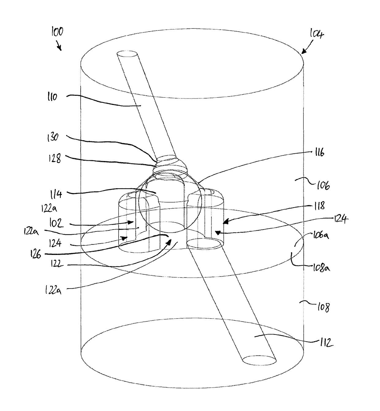
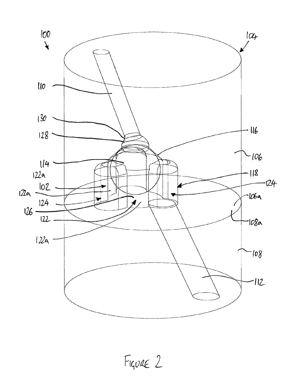
[0031]A non-return valve assembly 100 according to the present invention, for use in a high-pressure fuel injection system, is shown in FIGS. 2 to 4.

[0032]Referring initially to FIGS. 2 and 3, the valve assembly 100 comprises a valve chamber 102 defined within a valve housing 104. The valve housing 104 comprises a first housing body 106 and a second housing body 108. An inlet passage 110 is formed in the first housing body 106 to deliver fuel into the valve chamber 102 from the pump chamber (not shown) of an associated high-pressure fuel pump. An outlet passage 112 is formed in the second housing body 108 to convey fuel from the valve chamber 102 to a high-pressure fuel rail (not shown).

[0033]The valve assembly 100 further comprises a valve ball 114, which is received within the valve chamber 102. The valve ball 114 is moveable within the chamber 102 to engage with a valve seat 116 formed in the first housing body 106 where the inlet passage 110 opens into the valve chamber 102. As ...

second embodiment

[0057]It will be appreciated that several variations and modifications of the present invention are possible. By way of example, FIG. 5 shows a non-return valve assembly 200 according to the invention which differs from the valve assembly 100 of FIGS. 2 to 4 in the shape of the valve chamber. The remaining features common to both embodiments, indicated where appropriate with common reference numerals, will not be described in detail.

[0058]In the valve 200 of FIG. 5, the valve chamber 202 includes a central region 122 defined by three part-cylindrical guide portions 122a, as in the first embodiment of the invention. However, in this second embodiment, the lobes 124, 224 of the valve chamber 202 are of unequal dimensions.

[0059]One of the lobes 124, into which the outlet passage 112 opens, is defined by an outlying part-cylindrical portion 124a of the valve chamber wall 118, joined to the central region 122 by a pair of parallel planar wall portions 124b.

[0060]The remaining two lobes ...


PUM


Abstract

A non-return valve assembly for a high-pressure fuel injection system is disclosed. The valve comprises a valve chamber defined in part by a first body and in part by a second body and defining a valve chamber wall, an inlet passage formed in the first body and opening into the valve chamber at a valve seat defined by the first body, an outlet passage, and a valve ball received within the valve chamber and engageable with the valve seat so as to interrupt fluid flow from the outlet passage to the inlet passage through the valve chamber. The valve chamber wall comprises a plurality of guide portions to guide the valve ball in substantially linear movement within the valve chamber.

Description

CROSS REFERENCE TO RELATED APPLICATIONS[0001]This application is a national stage application under 35 U.S.C. 371 of PCT Application No. PCT / EP2013 / 055711 having an international filing date of 19 Mar. 2013, which designated the United States, which PCT application claimed the benefit of European Patent Application No. 12163309.3 filed on 5 Apr. 2012, the entire disclosure of each of which are hereby incorporated herein by reference.FIELD OF THE INVENTION[0002]The present invention relates to a valve assembly for use in a high-pressure fuel injection system. In particular, but not exclusively, the invention relates to a valve assembly for preventing back-flow of fuel from a fuel accumulator to a fuel pump.BACKGROUND TO THE INVENTION[0003]FIG. 1 of the accompanying drawings illustrates, schematically, a fuel injection system of the common-rail type for use in an internal combustion engine, for example as described in EP-A-1921307. An accumulator volume for fuel, known as a common rai...

Claims


Application Information

Patent Timeline
Patent Type & Authority Patents(United States)
IPC IPC(8): F16K15/00F02M63/02F02M63/00F16K17/164F16K15/04F02M69/46F02M47/02
CPCF16K17/164F02M63/0054F02M63/0071F02M63/0225F16K15/04F16K15/048Y10T137/774F16K27/0245F16K27/0209
Inventor GRAHAM, MARK S.TREMETHICK, TRISTAN P.MALLELA VISWA, VENKATA RAVINDRAWILLIAMS, RYAN
Owner DELPHI TECH IP LTD
Why Eureka
Try Eureka