
Magnetic tape with specific servo pattern edge shape and magnetic tape device using same

a technology of magnetic tape and edge shape, which is applied in the field of magnetic tape and magnetic tape device, can solve the problems of difficulty in accurately positioning the magnetic head, and achieve the effect of reducing the accuracy of the head positioning of the timing-based servo system results, and increasing the capacity of the servo write head

Active Publication Date: 2017-09-26
FUJIFILM CORP
View PDF10 Cites 110 Cited by
  • Summary
  • Abstract
  • Description
  • Claims
  • Application Information

AI Technical Summary

Benefits of technology

This patent text describes a technique for improving the positioning precision of a magnetic tape head when running in a drive to record or play information on the tape. This is achieved by using a servo signal that is formed on the magnetic layer and read by a servo head. The position of the head is controlled based on the servo signal to ensure accurate tracking of the data track on the tape, regardless of any fluctuations in the position of the tape. This results in improved accuracy in recording and playing information on the tape. Additionally, the text describes a method for measuring misalignment width and shifting of the servo pattern using a specific value called L99.9-L0.1. The patent proposes a magnetic tape with a servo pattern that enhances the precision of the head positioning during running in a drive. This would improve the performance and reliability of magnetic tape devices for recording and playback of information.

Problems solved by technology

However, when the width of the data track is narrowed and the magnetic tape is run within a drive to record and / or reproduce a magnetic signal, positional fluctuation in the direction of width of the magnetic tape makes it difficult for the magnetic head to accurately follow the data track, which tends to cause errors during recording and / or reproduction.

Method used


Image

  • Magnetic tape with specific servo pattern edge shape and magnetic tape device using same
  • Magnetic tape with specific servo pattern edge shape and magnetic tape device using same
  • Magnetic tape with specific servo pattern edge shape and magnetic tape device using same

Examples


example 1

[0119]1. Preparation of Alumina Dispersion (Abrasive Liquid)

[0120]To 100.0 parts of alumina powder (HIT-70 made by Sumitomo Chemical Co., Ltd.) with an alpha conversion rate of about 65% and a Brunauer-Emmett-Teller (BET) specific surface area of 30 m2 / g were admixed 3.0 parts of 2,3-dihydroxynaphthalene (made by Tokyo Chemical Industry Co., Ltd.), 31.3 parts of a 32% solution (the solvent being a mixed solvent of methyl ethyl ketone and toluene) of polyester polyurethane resin (UR-4800 (polar group content: 80 meq / kg) made by Toyobo (Japanese registered trademark) having polar groups in the form of SO3Na groups, and 570.0 parts of a mixed solution with a 1:1 (weight) ratio of methyl ethyl ketone and cyclohexanone as solvent and the mixture was dispersed for 5 hours in a paint shaker in the presence of zirconia beads. Following dispersion, the dispersion and the beads were separated with a mesh to obtain an alumina dispersion.

[0121]2. Formula of the Magnetic Layer-Forming Compositio...

examples 2 to 7

, Comparative Examples 1 to 9

[0148]Table 1 gives the ferromagnetic powders, bead dispersion times during preparation of the magnetic layer-forming composition, whether orientation processing was conducted, and the leakage magnetic field of the servo write head used to prepare the magnetic tapes of Examples 2 to 7 and Comparative Examples 1 to 9. For the servo write head, the stronger the leakage magnetic field, the greater the capacity to record the servo pattern. Three servo write heads with different leakage magnetic fields were employed in the Examples and Comparative Examples. Table 1 records the servo write head recording capacity in the order of lowest to highest leakage magnetic field as low, medium, or high.

[0149]For the items shown in Table 1 and where ferromagnetic metal powders were employed as the ferromagnetic powder, with the exception that kneading and dilution were conducted prior to dispersion by kneading the various components of the magnetic liquid in an open knea...


PUM

PropertyMeasurementUnit
temperatureaaaaaaaaaa
magnetizationaaaaaaaaaa

Abstract

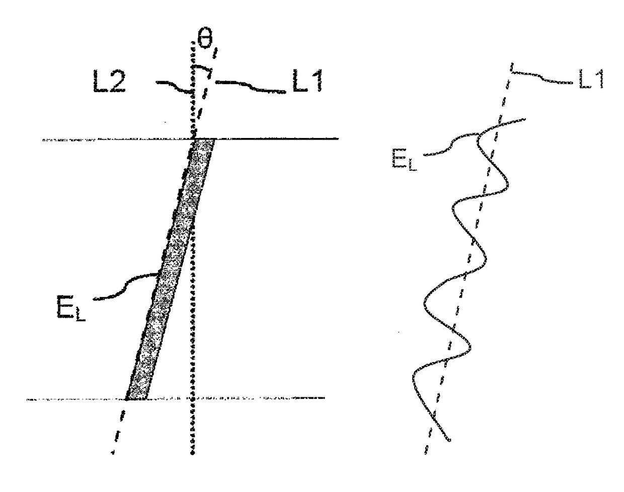
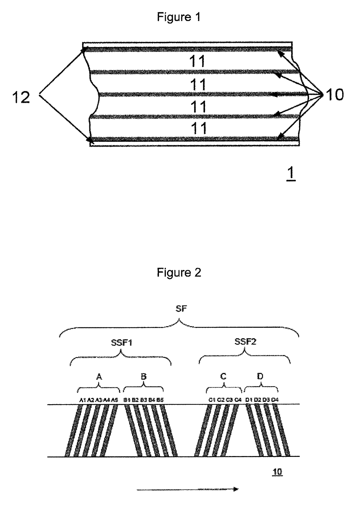
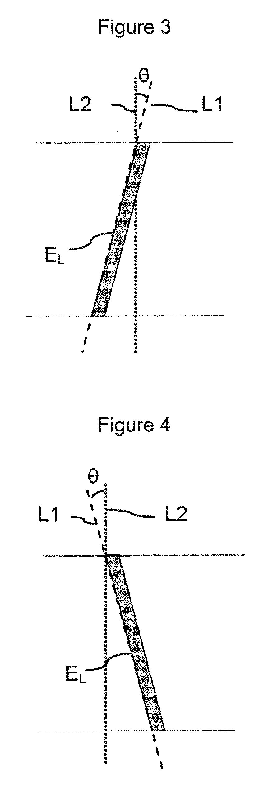
The magnetic tape has a magnetic layer containing ferromagnetic powder and binder on a nonmagnetic support, wherein the coercive force measured in the longitudinal direction of the magnetic tape is less than or equal to 167 kA / m, a timing-based servo pattern is present on the magnetic layer, and the edge shape specified by observing the timing-based servo pattern with a magnetic force microscope is a shape in which the difference between the value L99.9 of the 99.9% cumulative distribution function of the width of misalignment from the ideal shape in the longitudinal direction of the magnetic tape and the value L0.1 of the 0.1% cumulative distribution function, L99.9−L0.1, is less than or equal to 180 nm.

Description

CROSS-REFERENCE TO RELATED APPLICATIONS[0001]This application claims priority under 35 U.S.C 119 to Japanese Patent Application No. 2015-254192 filed on Dec. 25, 2015. The above application is hereby expressly incorporated by reference, in its entirety.BACKGROUND OF THE INVENTION[0002]Field of the Invention[0003]The present invention relates to a magnetic tape and a magnetic tape device.[0004]Discussion of the Background[0005]Magnetic recording media include tape-shaped media and disk-shaped media. Magnetic recording media in the form of tapes, that is, magnetic tapes, also referred to simply as “tapes” hereinafter, are primarily employed in storage applications such as data-back and archiving. A magnetic signal is normally recorded on the data band of a magnetic tape when recording information on a magnetic tape. Thus, a data track is formed on a data band running in the longitudinal direction.[0006]With the immense increase in the amount of information in recent years, higher reco...

Claims


Application Information

Patent Timeline
Patent Type & Authority Patents(United States)
IPC IPC(8): G11B5/78G11B5/70G11B5/592
CPCG11B5/78G11B5/5928G11B5/70G11B5/584
Inventor KASADA, NORIHITOKANEKO, TETSUYA
Owner FUJIFILM CORP
Learn More