Fire resistant coaxial cable

a coaxial cable, fire-resistant technology, applied in the direction of cables, insulated conductors, inorganic insulators, etc., can solve the problems of porous ceramic structure, brittle resistance dielectric,

Active Publication Date: 2017-09-26
AMERICAN FIRE WIRE INC
View PDF9 Cites 15 Cited by
  • Summary
  • Abstract
  • Description
  • Claims
  • Application Information

AI Technical Summary

Benefits of technology

[0033]The method can include resting the coaxial cable on a metal surface, wherein the burning of the outer jacket exposes the ceramifiable silicone rubber inner jacket or the ceramic fiber

Problems solved by technology

That is, the resilient dielectric turns

Method used


Image

  • Fire resistant coaxial cable
  • Fire resistant coaxial cable
  • Fire resistant coaxial cable

Examples


Embodiment Construction

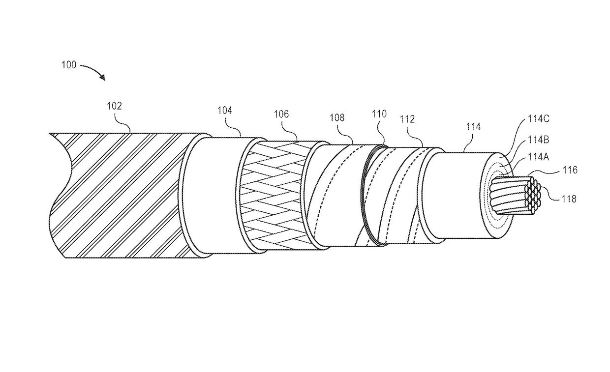
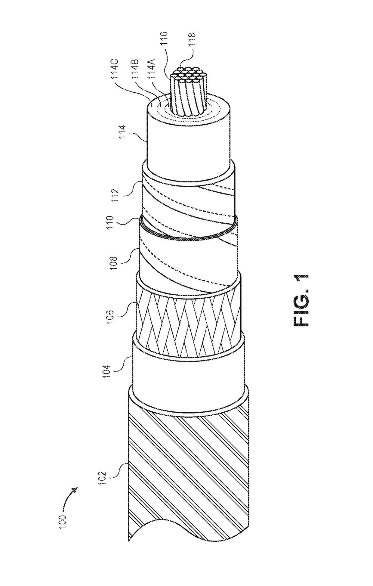
[0042]Fire resistant coaxial cable is described. Some embodiments of the cable can survive two hours in fire conditions of 1010° C. (1850° F.), maintaining or increasing dielectric spacing and avoiding shorting to allowing radio frequency (RF) signals to pass. This coaxial cable may be suitable for meeting building codes for a distributed antenna system (DAS) without the need for fire-protective soffits, conduits, or other expensive shielding.

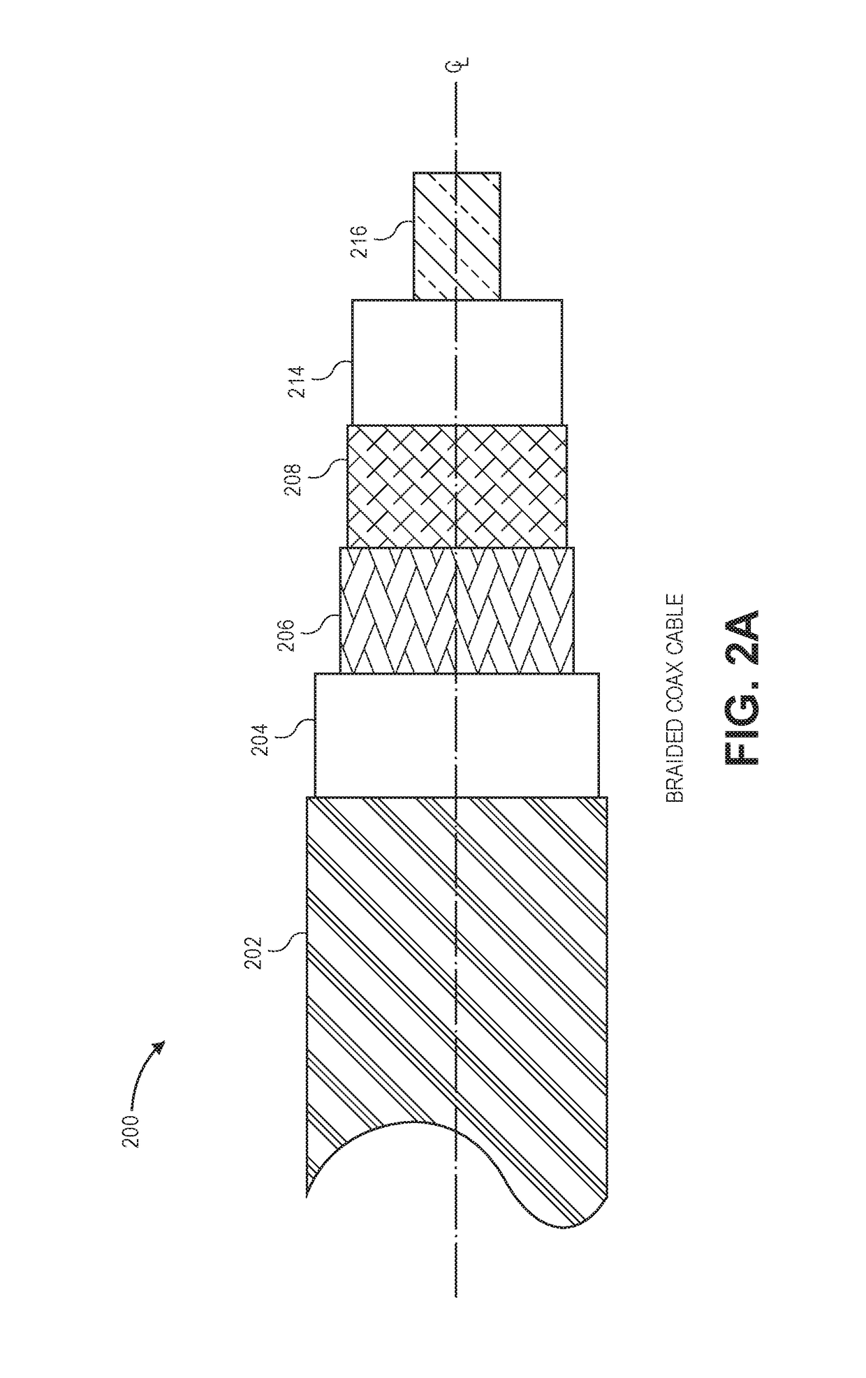
[0043]Flexible braided cables and durable corrugated cables, among other cable types, are described. Braided cables as described can be suitable for replacing 50Ω LMR®-600 flexible communication cable manufactured by Times Microwave Systems, Inc. of Wallingford, Conn., United States.

[0044]A “ceramifiable” material includes a material that turns from a flexible material into a ceramic when exposed to high temperatures, such as over 425° C., 482° C., 1010° C., or as otherwise known in the art. The material can be a composition of component materi...


PUM


Abstract

A fire-resistant coaxial cable is described in which the dielectric between the central conductor and outer coaxial conductor can ceramify under high heat. The dielectric is composed of a ceramifiable silicone rubber, such as that having a polysiloxane matrix with inorganic flux and refractory particles. An outer wrap of ceramic fiber yarn surrounds the outer conductor and continues to insulate it from the outside if a low smoke zero halogen jacket burns away. Embodiments include those with durable corrugated outer conductors or flexible braided outer conductors. Methods of testing and installation are described.

Description

CROSS-REFERENCES TO RELATED APPLICATIONS[0001]Not ApplicableCOPYRIGHT NOTICE[0002]A portion of the disclosure of this patent document contains material which is subject to copyright protection. The copyright owner has no objection to the facsimile reproduction by anyone of the patent document or the patent disclosure, as it appears in the Patent and Trademark Office patent file or records, but otherwise reserves all copyright rights whatsoever.BACKGROUND[0003]1. Field of the Invention[0004]The present application generally relates to electrical cables, including selection of materials for their conductive, insulating, or dielectric properties. Specifically, the application is related to fire-resistant co-axial cables with ceramifiable silicone rubber or ceramic fiber dielectric between the conductors and outside of the outer conductor.[0005]2. Description of the Related Art[0006]Since the Sep. 11, 2001 attacks on the World Trade Center and Pentagon, there has been a world-wide empha...

Claims


Application Information

Patent Timeline
IPC IPC(8): H01B7/295H01B7/20H01B11/18H01B3/12H01B7/22H01B7/02
CPCH01B7/295H01B7/20H01B11/1813H01B7/228H01B7/0275H01B3/12
Inventor ROGERS, WILLIAM E.
Owner AMERICAN FIRE WIRE INC
Why Eureka
Try Eureka