Compact fuse support
a fuse support and compact technology, applied in the field of switchgear and similar electrical isolation equipment, can solve the problems of requiring space in the switchgear for direct mounting of fuses onto the voltage transformer, difficult, if not impossible, to mount fuses directly onto the voltage transformer in small footprint switchgear, and achieve the effect of sufficient spacing
- Summary
- Abstract
- Description
- Claims
- Application Information
AI Technical Summary
Benefits of technology
Problems solved by technology
Method used
Image

Examples
Embodiment Construction
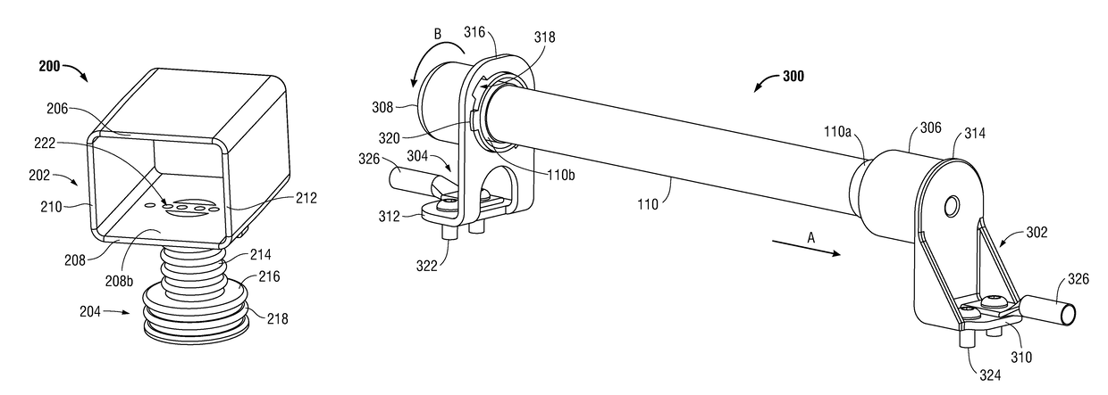
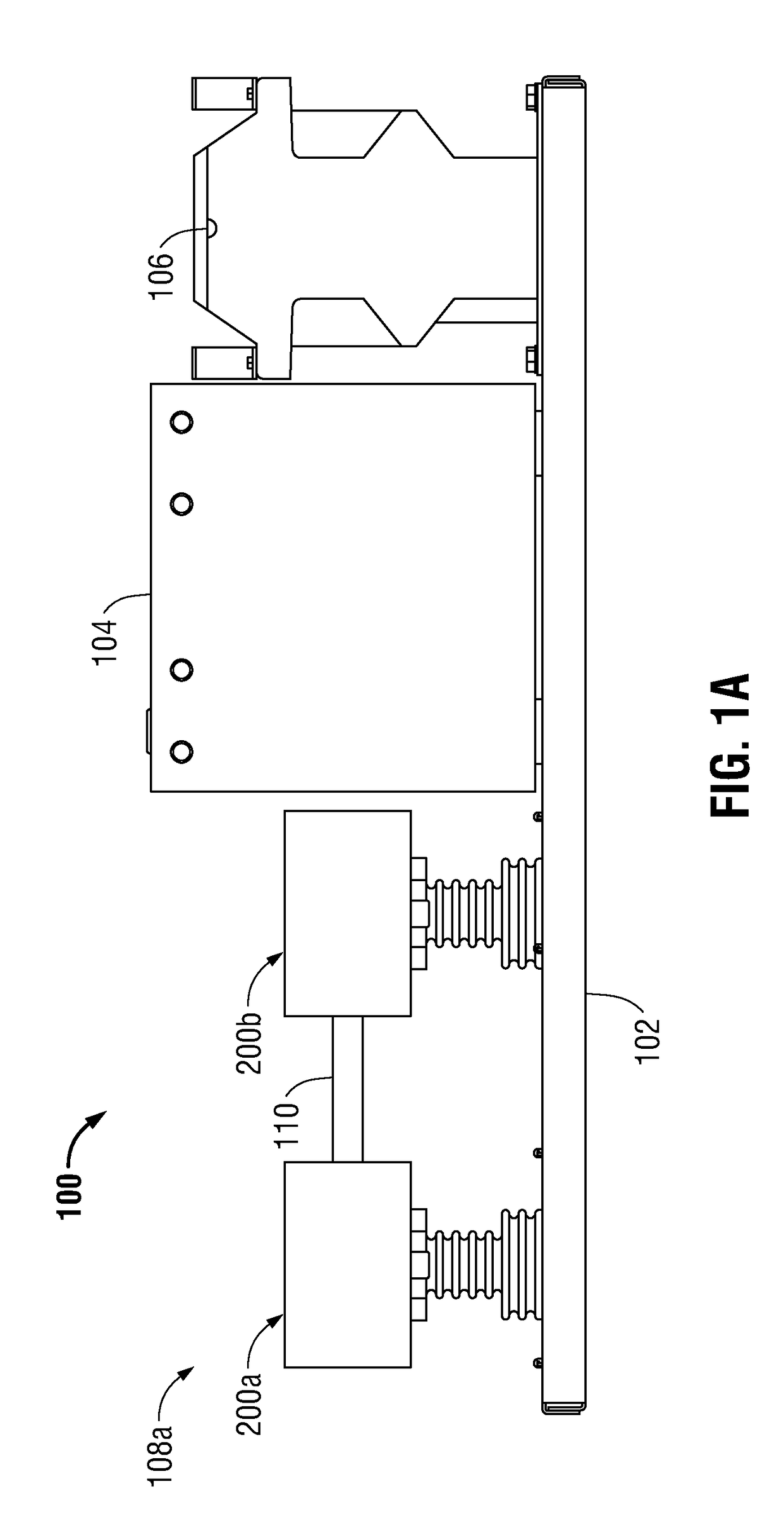
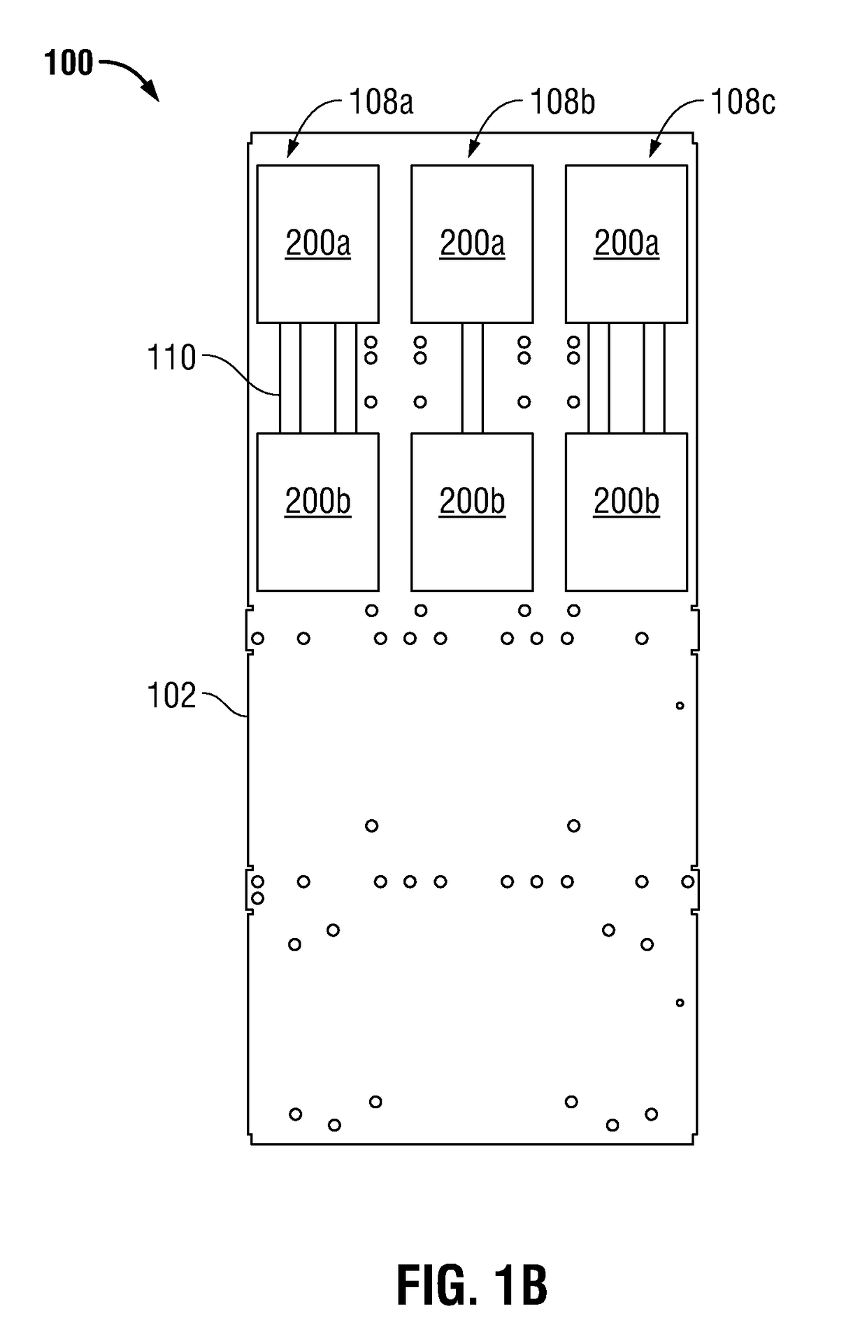
[0006]The embodiments disclosed herein are directed to a method and apparatus for mounting fuses that protect transformers in switchgear and similar electrical isolation equipment. The method and apparatus provide a nonconductive fuse support that allows the tubular fuses to be mounted separately from, instead of directly on, the transformers. Two such fuse supports may be used to support a fuse, each fuse support supporting one fuse terminal. Alternatively, each fuse support may support two fuse terminals so dual fuses may be supported by the same pair of fuse supports. The fuse supports substantially surround the fuse terminals to provide an insulating barrier that helps prevent electrical discharge and also ensure sufficient spacing between the fuse terminals and ground or other conductors in the switchgear. Such an arrangement allows the fuses and transformers to fit within a reduced space in the switchgear and similar electrical isolation equipment while complying with industry...
PUM
 Abstract
Description
Claims
Application Information
PatSnap Eureka turns technology decisions into work you can execute. Powered by our Innovation Knowledge Graph, it runs expert workflows across engineering, life sciences, materials and intellectual property. Get your review-ready output in minutes.


