
Osteoconductive and osteoinductive implant for augmentation, stabilization, or defect reconstruction

a technology of osteoinduction and osteoconductive implants, applied in bone implants, prostheses, medical science, etc., can solve the problem of no structural implants that offer osteoinduction capabilities

Inactive Publication Date: 2017-10-03
UNIV OF SOUTH FLORIDA
View PDF8 Cites 0 Cited by
  • Summary
  • Abstract
  • Description
  • Claims
  • Application Information

AI Technical Summary

Problems solved by technology

Bone allografts, polylactic acid isomers, and polyglycolic acid isomers have established independent efficacy in the treatment of bone defects and bone reconstruction in multiple clinical situations; however, there are currently no structural implants that offer osteoconductive and osteoinductive capabilities.

Method used


Image

  • Osteoconductive and osteoinductive implant for augmentation, stabilization, or defect reconstruction
  • Osteoconductive and osteoinductive implant for augmentation, stabilization, or defect reconstruction
  • Osteoconductive and osteoinductive implant for augmentation, stabilization, or defect reconstruction

Examples


example 1

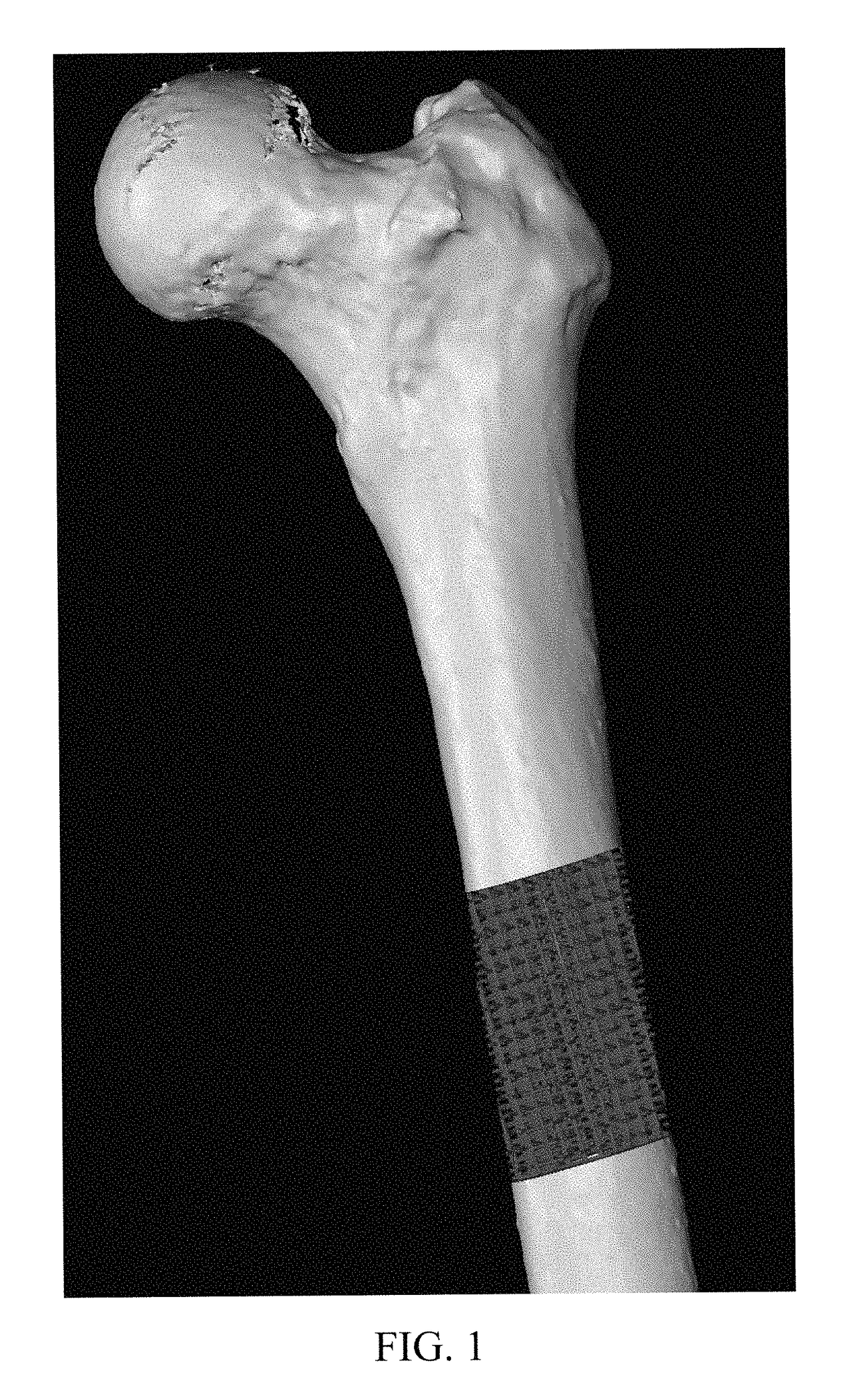
or Stabilization of a Long Bone (Femur)

[0036]FIG. 1 shows an implant of the present invention providing stabilization of a long bone.

example 2

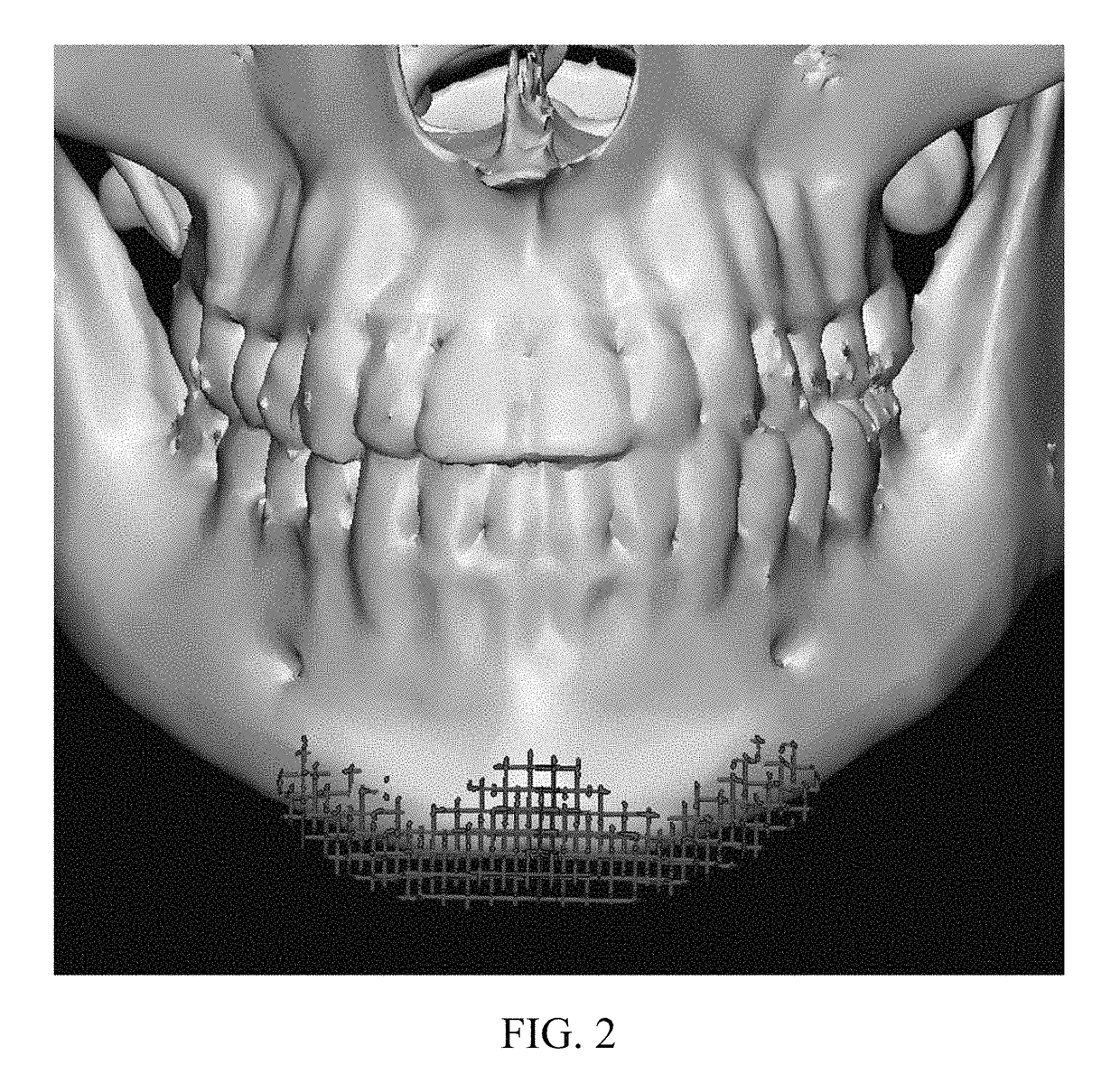
or Augmentation of a Chin

[0037]FIG. 2 shows an implant of the present invention providing chin augmentation.

example 3

or Zygoma Reconstruction

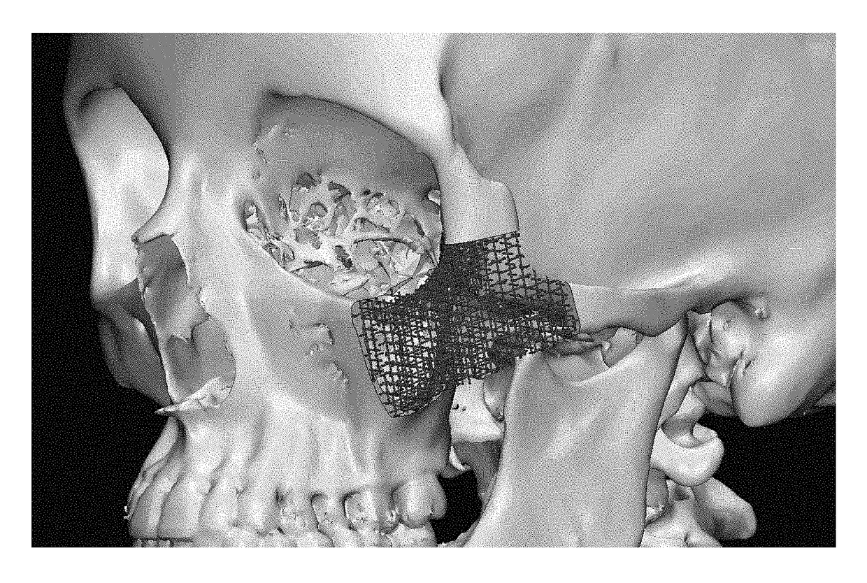
[0038]FIG. 3 shows an implant of the present invention placed in position for zygoma reconstruction viewed from the face of the skull. FIG. 4 shows the implant shown in FIG. 3 viewed from the side of the skull.


PUM

PropertyMeasurementUnit
bioresorbableaaaaaaaaaa
shapeaaaaaaaaaa
lattice structureaaaaaaaaaa

Abstract

Aspects of the present invention provide implants for augmentation, stabilization, or defect reconstruction of bone tissue, comprising a scaffold portion structured to provide shape to the implant, the scaffold portion comprising one or more of the following: one or more polylactic acid isomer; one or more polyglycolic acid isomer; and / or allogenic bone material, or similar compound.

Description

BACKGROUND OF THE INVENTION[0001]Bone allografts, polylactic acid isomers, and polyglycolic acid isomers have established independent efficacy in the treatment of bone defects and bone reconstruction in multiple clinical situations; however, there are currently no structural implants that offer osteoconductive and osteoinductive capabilities.BRIEF SUMMARY OF THE INVENTION[0002]Aspects of the present invention combine allogenic bone material, such as, e.g., demineralized bone matrix or bone allograft; polylactic acid (PLA) isomers; and polyglycolic acid (PGA) isomers, or similar compounds, such as, for example, a mixture of PLA and PGA polymers (PLGA polymer) or polydioxanone (PDS) into a single implant both in plate configurations and in three-dimensional (3D) configurations, whether as a predetermined standard arrangement or customized form. Implants of the present invention address skeletal reconstruction through replacing, augmenting, or buttressing the patient's native bone.[000...

Claims


Application Information

Patent Timeline
Patent Type & Authority Patents(United States)
IPC IPC(8): A61F2/28A61L27/00
CPCA61F2/28A61L27/00A61F2230/00A61L27/3608A61L27/446A61L27/46A61L27/58C08L67/04
Inventor CHING, JESSICA ALLENFORD, JONATHAN MICHAELDECKER, SUMMER JOY
Owner UNIV OF SOUTH FLORIDA
Learn More