Purging and sealing-reductant delivery unit for selective catalytic reduction systems

a delivery unit and catalytic reduction technology, applied in the direction of valve housing, machines/engines, mechanical equipment, etc., can solve the problems of high nitrogen oxide emissions of lean-burn engines, difficult treatment, and damage to injection units, so as to improve the purging efficiency of rdu, prevent component damage during freezing conditions, and improve the sealing performance of the unit

Active Publication Date: 2017-10-03
VITESCO TECH USA LLC
View PDF43 Cites 8 Cited by
  • Summary
  • Abstract
  • Description
  • Claims
  • Application Information

AI Technical Summary

Benefits of technology

[0009]The RDU delivers a reductant carrier (e.g. aqueous urea solution) to the engine exhaust system. The solution is transformed into ammonia which then reacts with the exhaust oxides of nitrogen in a catalytic environment to produce nitrogen and H2O. One type of urea, commercially known as AdBlue, has a freezing point of −11° C. In order to prevent component damage during freezing conditions, AdBlue injection systems remove fluid from the injector by purging. This invention improves the purging efficiency of the RDU in addition to improving the sealing performance of the unit.
[0010]It is an object of this invention to reduce the fluid volume to be evacuated from the injector. It is another object of this invention to provide an additional sealing barrier to reduce the sealing load of the existing sealing elements. The feature consists of an additional sealing device having a stopper element (also referred to as a “plug”) that is pressed into the upper valve body of the injector, and a ring seal. The injector is then installed into the injector cup ensuring that the ring seal of the sealing device is compressed between a flange portion formed as part of the upper valve body of the injector, and the injector cup.
[0013]In one embodiment, the present invention is an injector having a sealing device, where the injector includes an upper valve body having a flange portion, and an O-ring surrounding and in contact with an outer surface of the upper valve body. The injector also includes a cap having a large diameter portion, a small diameter portion and a circumferential flange integrally formed together, where the large diameter portion of the cap substantially surrounds the O-ring such that an inner surface of the large diameter portion of the cap contacts the O-ring, at least partially compressing the O-ring, providing a sealing function between the O-ring and the large diameter portion of the cap and between the O-ring and the outer surface of the upper valve body.
[0015]The injector also includes an inlet, and an aperture formed as part of the inlet is substantially aligned with the aperture of the stopper element and the aperture of the ring seal, such that fluid is allowed to pass through the inlet, the stopper element, and the ring seal to pass through the valve body. Also formed as part of the inlet is a reduced diameter portion, the reduced diameter portion is received into and surrounded by the small diameter portion of the cap. Each of the plurality of ribs are in contact with the inner surface of the circumferential flange, and the lower surface of the circumferential portion of the ring seal is in contact with the flange portion to provide a sealing function, preventing the O-ring from being exposed to fluid during an SCR operation.

Problems solved by technology

Lean-burn engines exhibit high levels of nitrogen oxide emissions (NOx), that are difficult to treat in oxygen-rich exhaust environments characteristic of lean-burn combustion.
This expansion may cause damage to the injection unit, therefore, injection systems typically purge the injection unit when the engine shuts down to remove the fluid contained therein.
It has been found that the efficiency of this method is not 100%, i.e. a certain amount of fluid remains in the injection unit.
Although the amount of remaining fluid may not always be sufficient to risk damage to the injector upon freezing (expansion volume is available for the expanding ice), a risk remains that during engine hot soaks, the remaining fluid could be exposed to high temperature.
This high temperature exposure could result in the decomposition of the AUS-32 which would also cause damage to the injection unit.
However, in some injectors, there is a potential leak path for the AUS-32 past the installed O-ring which cooperates with the injector cup to provide a sealing function.
Although this sealing path created by the O-ring is typically sufficient for liquids, it has been found that AUS-32 solution is prone to breaching seals of this type in the form of creeping urea crystals.

Method used


Image

  • Purging and sealing-reductant delivery unit for selective catalytic reduction systems
  • Purging and sealing-reductant delivery unit for selective catalytic reduction systems
  • Purging and sealing-reductant delivery unit for selective catalytic reduction systems

Examples


Embodiment Construction

[0021]The following description of the preferred embodiment(s) is merely exemplary in nature and is in no way intended to limit the invention, its application, or uses.

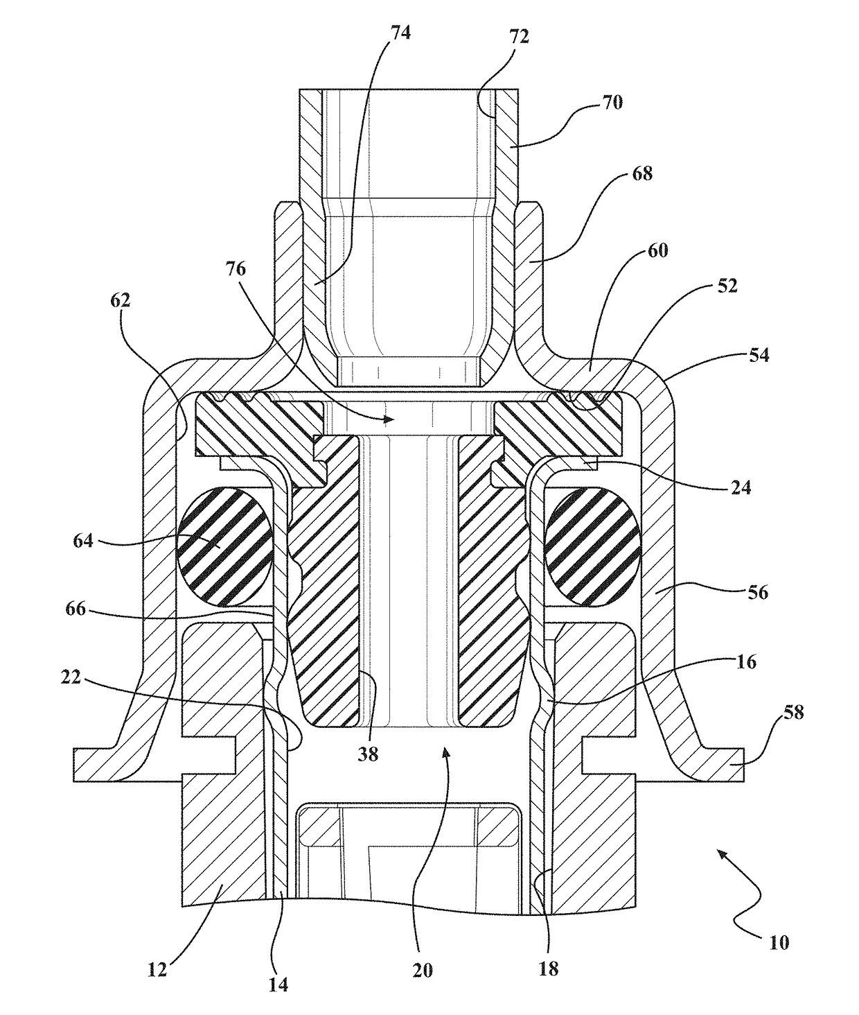
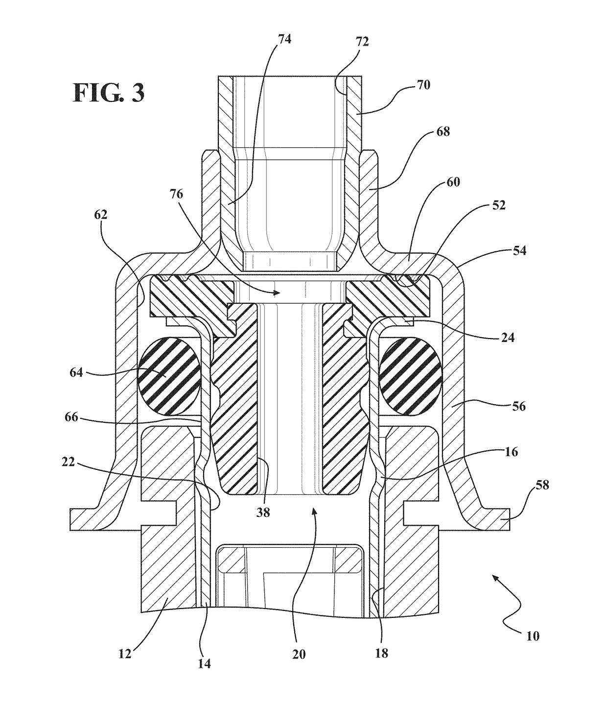
[0022]Referring now to the Figures generally, a portion of an injector having a seal device according to the present invention is shown generally at 10. The injector 10 includes a housing portion 12, which substantially surrounds an upper valve body 14. The housing portion 12 is hollow, and the upper valve body 14 has a notch 16 which is placed against the inner surface 18 of the housing portion 12, and connects the housing portion 12 and the valve body 14 through the use of an interference fit.

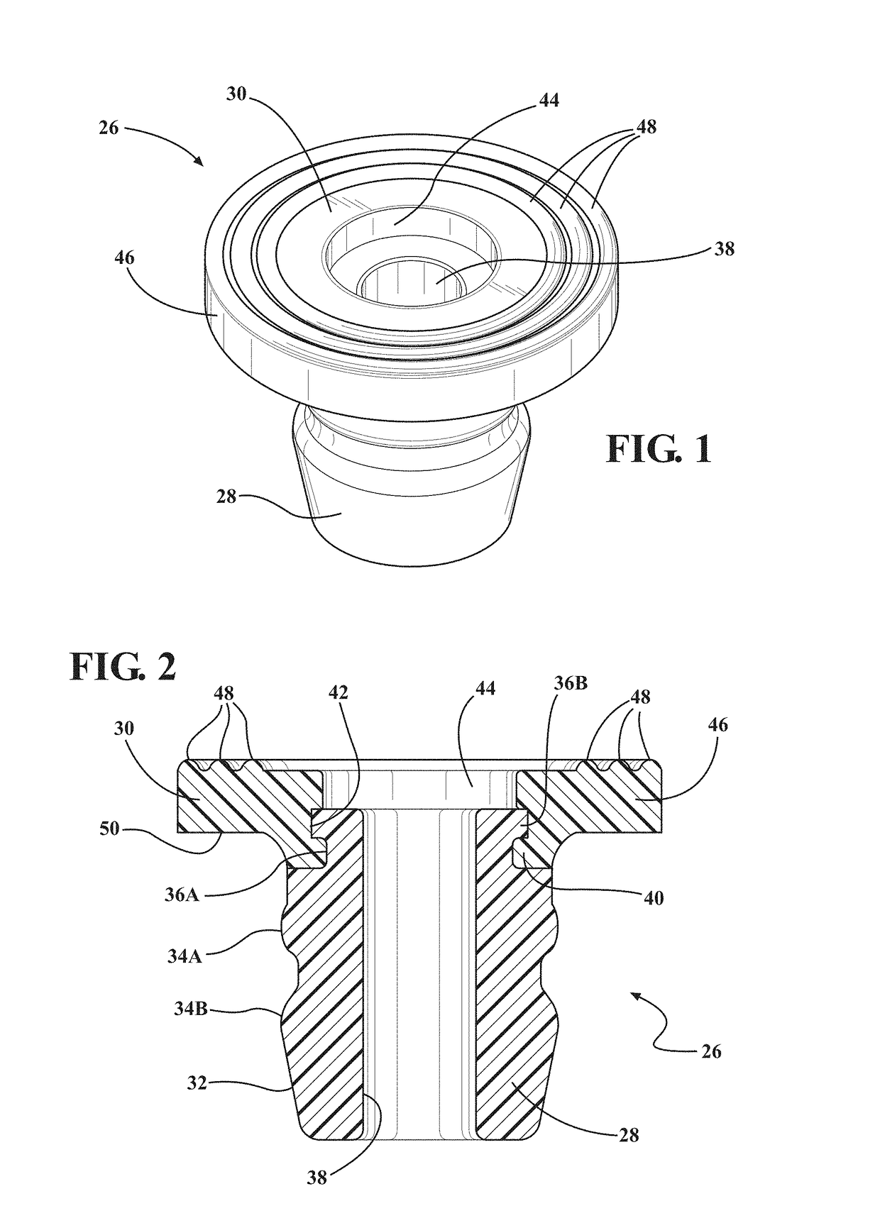
[0023]The upper valve body 14 is also hollow, and includes a cavity, shown generally at 20, and an inner surface 22. The upper valve body 14 also includes an upper flange 24, integrally formed as part of the upper valve body 14. Partially disposed in the cavity 20 is a sealing device, shown generally at 26. The sealing device 2...


PUM


Abstract

A sealing device which is used as part of an injector in a reductant delivery unit (RDU), where the RDU is part of a selective catalytic reduction (SCR) system for injecting diesel exhaust fluid (DEF) into an exhaust system, used for controlling exhaust emissions. This invention improves the purging efficiency of the RDU, in addition to improving the sealing performance of the unit by reducing the fluid volume to be evacuated from the injector, and provides an additional sealing barrier to reduce the sealing load of the existing sealing elements. An additional sealing device having a ring seal and a stopper element (also referred to as a “plug”) is pressed into the upper valve body of the injector, which results in a reduced fluid volume that is left behind after a purging event, due to the reduced initial volume at the beginning of the purge.

Description

FIELD OF THE INVENTION[0001]The present invention relates generally to a sealing feature that is used as part of an injector for reducing the fluid volume to be evacuated from the injector, and to provide a sealing barrier to reduce the sealing load.BACKGROUND OF THE INVENTION[0002]New emissions legislation in Europe and North America is driving the implementation of new exhaust aftertreatment systems, particularly for lean-burn technologies such as compression-ignition (diesel) engines, and stratified-charge spark-ignited engines (usually with direct injection) that are operating under lean and ultra-lean conditions. Lean-burn engines exhibit high levels of nitrogen oxide emissions (NOx), that are difficult to treat in oxygen-rich exhaust environments characteristic of lean-burn combustion. Exhaust aftertreatment technologies are currently being developed that treat NOx under these conditions.[0003]One of these technologies includes a catalyst that facilitates the reactions of ammo...

Claims


Application Information

Patent Timeline
Patent Type & Authority Patents(United States)
IPC IPC(8): F01N3/20F16K27/00
CPCF16K27/00F01N3/2066F01N2610/02F01N2610/1453F01N2610/1493Y02T10/24Y02T10/12
Inventor VAN VUUREN, WILLEM NICOLAASBUGOS, STEPHEN C
Owner VITESCO TECH USA LLC
Why Eureka
Try Eureka