Device for purging tapping scrap iron on engine cylinder head production line

A technology for engine cylinder head and engine block, which is applied in the direction of tangent devices, tangent machines, metal processing machinery parts, etc., can solve the problems of affecting the precision of finishing machining, high labor intensity of workers, and low operation efficiency.

Pending Publication Date: 2019-08-09
Y & C ENGINE
View PDF0 Cites 2 Cited by
  • Summary
  • Abstract
  • Description
  • Claims
  • Application Information

AI Technical Summary

Problems solved by technology

[0002] Now the engine cylinder head is on the production line of the machining center, and it needs to go through many processes before it can be processed. Among them, threaded holes need to be drilled on both sides of the cylinder head. After drilling and tapping on the machining center, the deeper threaded holes will be Some iron filings remain. These iron filings must be cleaned up before entering the next process. If they are not cleaned, first: affect the machining accuracy of the next process. Iron filings directly affect the machining accuracy of finishi

Method used


Image

  • Device for purging tapping scrap iron on engine cylinder head production line
  • Device for purging tapping scrap iron on engine cylinder head production line
  • Device for purging tapping scrap iron on engine cylinder head production line

Examples


Embodiment 1

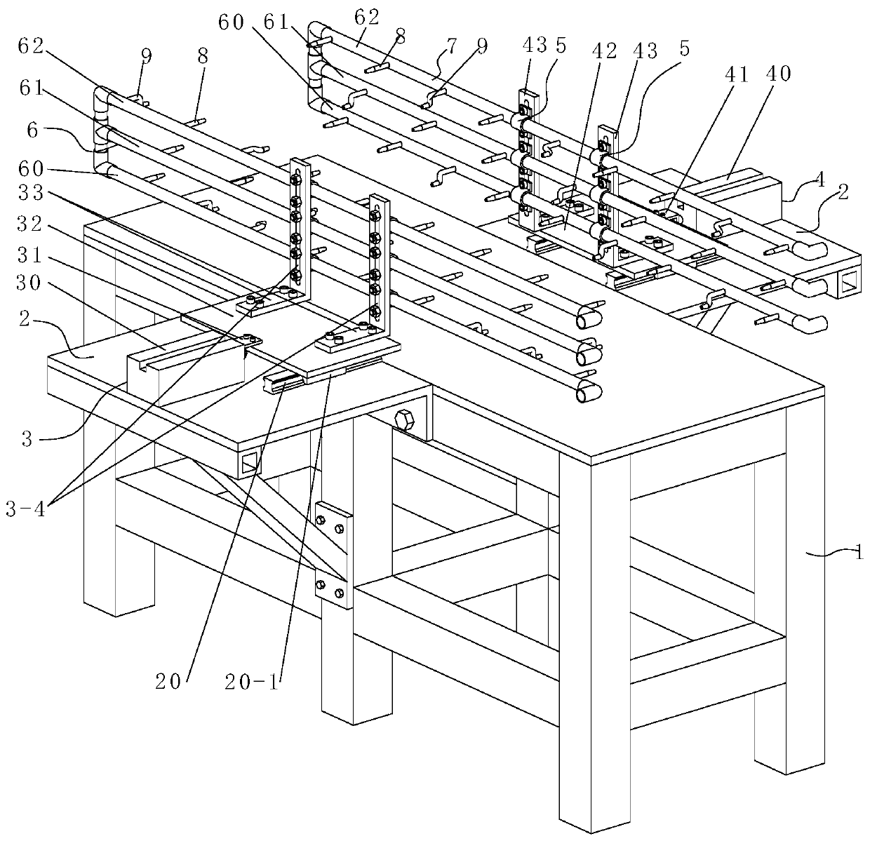
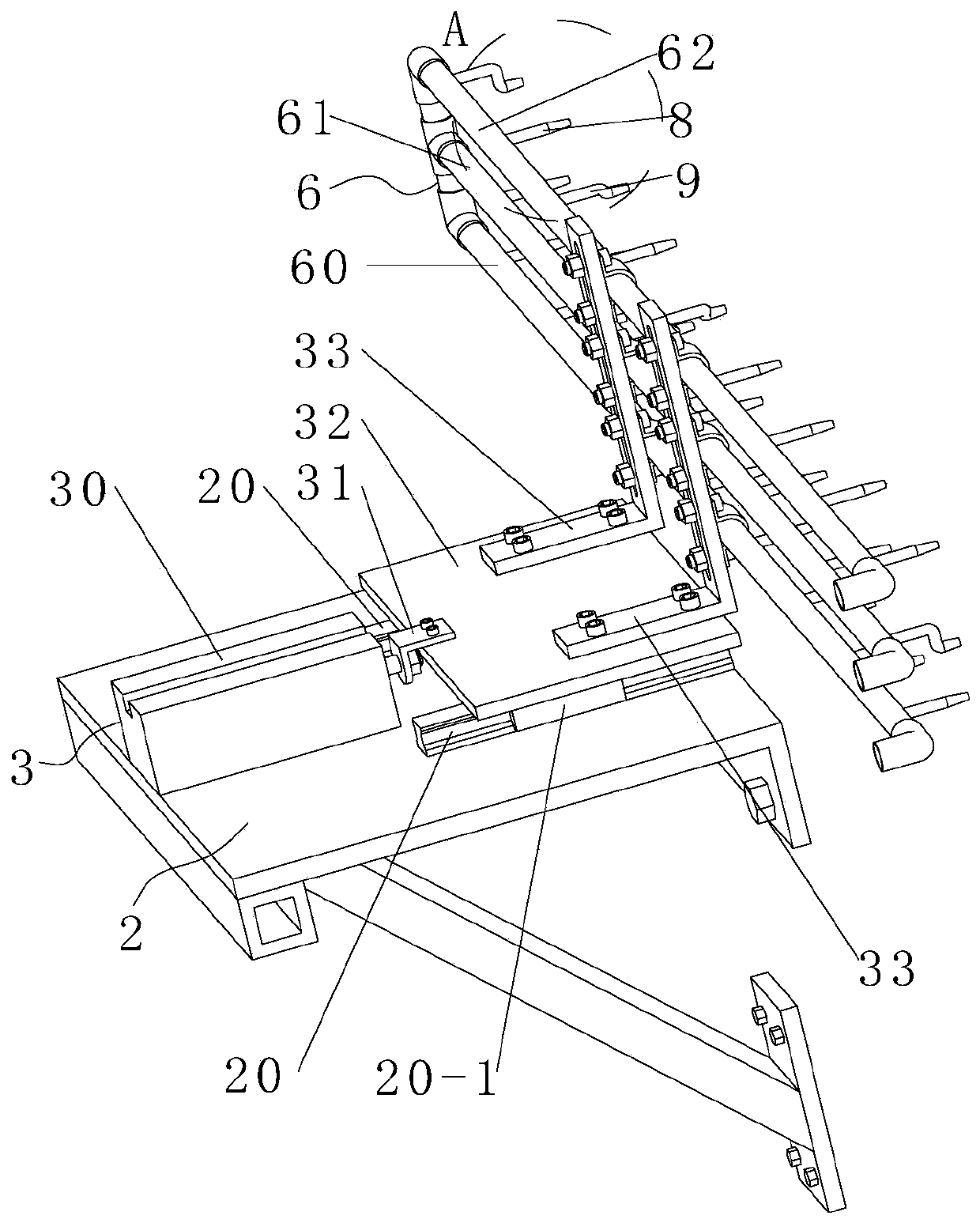
[0033] The tapping iron chip purging device on the engine cylinder head production line, after the cylinder head is transported to the blowing station workbench 1 on the production line, it stops moving, such as Figure 4As shown, when the solenoid valve is opened, the first cylinder 30 in the first drive system 3 and the second cylinder 40 in the second drive system 4 are ventilated respectively, so that the piston rod of the cylinder one 30 pushes the mobile platform through the buckle plate one 31 Plate 1 32 moves forward along the guide rail 20, and at the same time, the piston rod of cylinder 2 40 pushes the mobile platform plate 2 42 to move forward along the guide rail 20 through the fastening plate 2 41, and then the support 1 33 carries the first purge The piping system 6 moves forward, and the bracket 2 43 moves forward with the second purge piping system 7 until each blowing pipe 1 8 and blowing pipe 2 9 are respectively inserted into the deep threaded holes on both ...

Embodiment 2

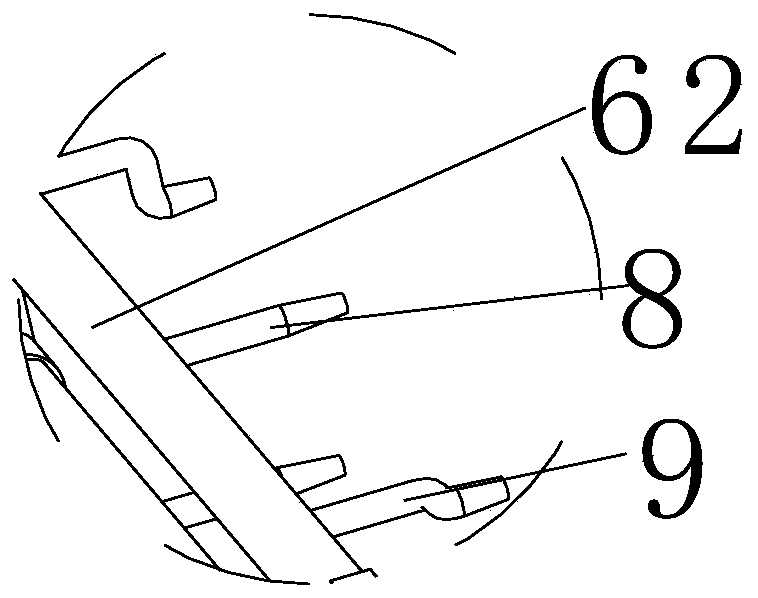
[0035] On the basis of Example 1, the first purge pipeline system 6 is fastened to the bracket one 33 through the half buckle, and the second purge pipeline system 7 is fastened to the bracket two 43 through the half buckle 5 , the first blowing pipe 8 and the second blowing pipe 9 are provided with a plurality, and are communicated with the first purge pipeline system 6 and the second purge pipeline system 7 respectively, and the first blowing pipe 8 and the second blowing pipe 9. The front ends are round table-shaped, and the first bracket 33 and the second bracket 43 are provided with long slots 3-4, which realizes the fine adjustment of the upper and lower positions of the first purge pipeline system 6 and the second purge pipeline system 7, ensuring that the cylinder head The uniformity of the gap left between the inner wall of the deep threaded hole and the outer wall of the front end of the air blowing pipe 8 and the air blowing pipe 2 9 ensures the smoothness of blowing...


PUM


Abstract

The invention discloses a device for purging tapping scrap iron on an engine cylinder head production line. The device is located on a purging station workbench and comprises a side platform, a firstdriving system, a second driving system, half buckles, a first purging pipeline system, a second purging pipeline system, a first purging pipe and a second purging pipe, wherein the side platform is fixedly connected with the side edge of the purging station workbench; the first driving system is fixedly connected with the upper end of one side of the side platform; the second driving system is fixedly connected with the upper end of the other side of the side platform; the first purging pipeline system is fixedly connected with a first support through the half buckles; the second purging pipeline system is fixedly connected with a second support through the half buckles; and the first purging pipeline system and the second purging pipeline system respectively communicate with the first purging pipeline system and the second purging pipeline system. The device has the advantages of having no influence on the machining precision of the next process and ensuring normal screwing of boltsduring assembly; labor force is liberated; and the metal dust does not affect the health of workers, the purging is high in efficiency and not forgotten.

Description

technical field [0001] The invention belongs to the technical field of automation equipment, in particular, the invention relates to a tapping iron chip purging device on an engine cylinder head production line. Background technique [0002] Now the engine cylinder head is on the production line of the machining center, and it needs to go through many processes before it can be processed. Among them, threaded holes need to be drilled on both sides of the cylinder head. After drilling and tapping on the machining center, the deeper threaded holes will be Some iron filings remain, these iron filings must be cleaned up before entering the next process, if not cleaned, first: affect the machining accuracy of the next process, iron filings directly affect the machining accuracy of finishing, including flatness, roughness, etc.; Second: The residual iron filings also affect the normal screwing of the bolts during assembly. [0003] At present, the method of removing some iron fil...

Claims


Application Information

Patent Timeline
IPC IPC(8): B23G1/44B23Q11/00
CPCB23G1/44B23G2240/08B23Q11/005
Inventor 倪勇王志新王欢陈凡凡侯应哲
Owner Y & C ENGINE
Why Eureka
Try Eureka