
Magnetic carrier

a carrier and magnet technology, applied in the field of magnet carriers, can solve the problems of increasing the burden on the developer in the development device, the development device is not viable, and the copying apparatus and the more excellent printers do not become viable nowadays, and achieve the effects of stable charge-providing ability, excellent wear resistance of coating films, and stable image density and tint fluctuation

Active Publication Date: 2017-10-03
CANON KK
View PDF58 Cites 22 Cited by
  • Summary
  • Abstract
  • Description
  • Claims
  • Application Information

AI Technical Summary

Benefits of technology

[0030]According to the present invention, the magnetic carrier that is excellent in wear resistance of a coating film even when used under a high-temperature and high-humidity environment for a long time period, that maintains a stable charge-providing ability, and that shows an image density and a tint fluctuation stable against a fluctuation from a high-humidity environment to a low-humidity environment can be obtained.

Problems solved by technology

Accordingly, unless art improvement in the performance of the developer can be achieved, a more excellent copying apparatus and a more excellent printer do not become viable nowadays.
Nowadays, however, a burden to be imposed on a developer in a developing device tends to increase owing to, for example, a reduction in developer volume in association with the downsizing of the developing device and an increase in stirring speed of the developer by an increase in output speed thereof.
As a result, particularly under a high-temperature and high-humidity environment, the spending of a toner or an external additive onto the surface of a magnetic carrier based on a water crosslinking force acting between the magnetic carrier and the toner progresses, and hence the charge-providing ability of the magnetic carrier reduces.
In addition, the adsorption of moisture to the surface of the magnetic carrier progresses to temporarily reduce the strength of the coating resin of the magnetic carrier, and hence the shaving of the coating resin of the magnetic carrier occurs to reduce its charge-providing ability.
Even when the developer disclosed in Japanese Patent Application Laid-Open No. 2005-49478 or Japanese Patent Application Laid-Open No. 2004-333931 is used, a crack occurs in a coating resin on the surface of the magnetic carrier owing to a severe burden on the developer in a recent developing device, and hence a wax derived from a toner adheres to the crack portion in some cases.
As a result, a fine particle derived from the toner adheres to the portion of the surface of the magnetic carrier to which the wax adheres, and hence the magnetic carrier cannot maintain carrier characteristics in its initial state and has insufficient durability.
In addition, moisture adsorption progresses from the crack portion occurring in the coating resin on the surface of the magnetic carrier to reduce its charge-providing ability.
In addition, in the case of each of Japanese Patent Application Laid-Open No. 2008-70662, Japanese Patent Application Laid-Open No. 2007-121911, and Japanese Patent Application Laid-Open No. 2009-229907, the shaving of a coating resin cannot be completely prevented.

Method used

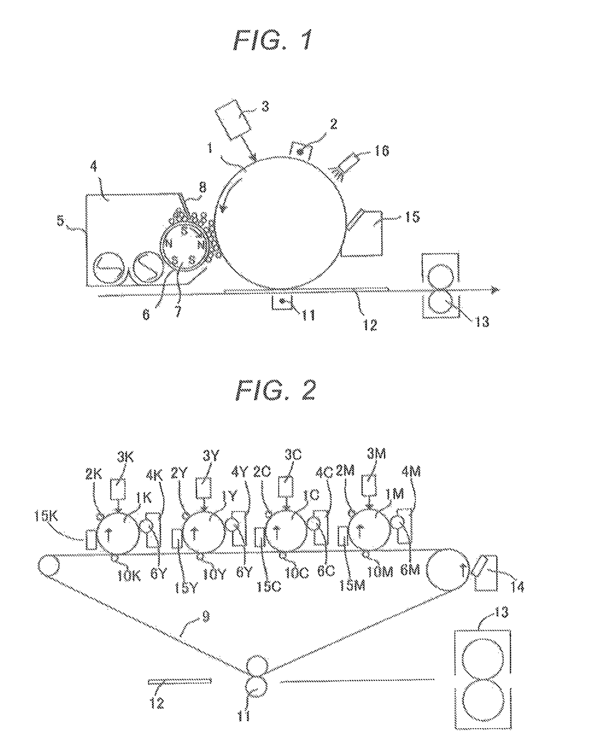
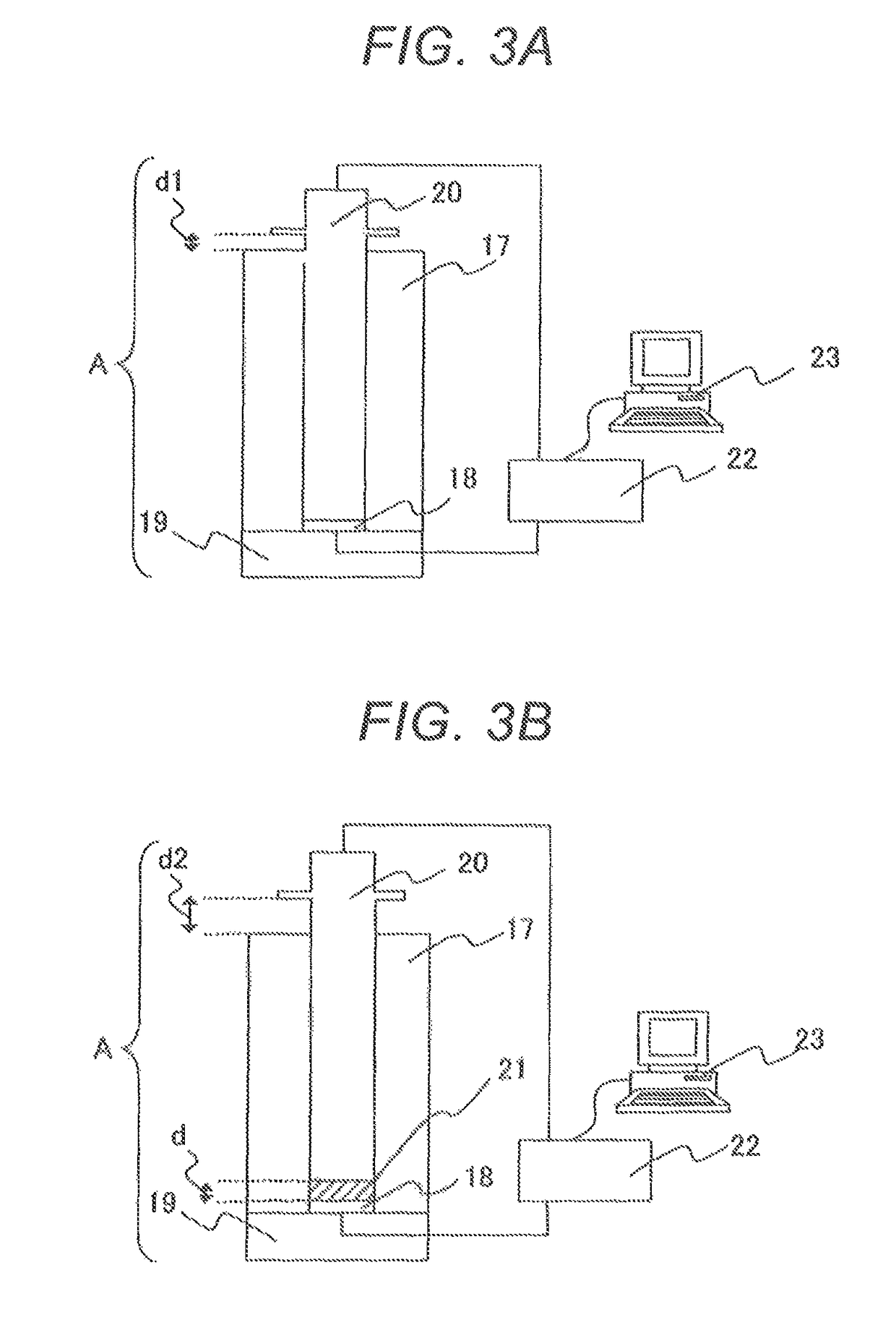

Image

  • Magnetic carrier
  • Magnetic carrier

Examples


example 1

[0314]10 Parts by mass of the cyan toner 1 was added to 90 parts by mass of the magnetic carrier 1, and the mixture was shaken with a shaker (Model YS-8D: manufactured by Yayoi Co., Ltd.) to prepare 300 g of a two-component cyan developer 1. Conditions for the shaking with the shaker were set to 200 rpm and 2 minutes. In addition, 300 g of a two-component developer 1 of each color was prepared in the same manner as in the two-component cyan developer 1 by using the toner 1 of each color.

[0315]Meanwhile, 90 parts by mass of the cyan toner 1 was added to 10 parts by mass of the magnetic carrier 1, and the contents were mixed in a normal-temperature and normal-humidity environment having a temperature of 23° C. and a humidity of 50% RH (hereinafter the phrase “normal-temperature and normal-humidity” is abbreviated as “N / N”) with a V-type mixer for 5 minutes to provide a replenishing cyan developer 1. In addition, a replenishing developer 1 of each color was obtained in the same manner ...

examples 2 and 4

[0375]Two-component developers 2 and 4, and replenishing developers 2 and 4 were prepared in the same manner as in Example 1 by using the magnetic carriers 2 and 4 at the same ratios as those of Example 1. Evaluations were performed in the same manner as in Example 1 except that the resultant two-component developers 2 and 4, and the resultant replenishing developers 2 and 4 were used.

[0376]Examples 2 and 4 differed from Example 1 in additive particle species and in method for the treatment of hydroxyl groups on the surfaces of additive particles, but in each of the examples, the moisture percentage change was small and hence extremely satisfactory results were obtained. The results of the evaluations are shown in Table 10-1 to Table 10-3.

example 3

[0377]A two-component developer 3 and a replenishing developer 3 were prepared in the same manner as in Example 1 by using the magnetic carrier 3 at the same ratios as those of Example 1. Evaluations were performed in the same manner as in Example 1 except that the resultant two-component developer 3 and the resultant replenishing developer 3 were used.

[0378]Example 3 differed from Example 1 in additive particle species and in method for the treatment of hydroxyl groups on the surfaces of additive particles, and hence influences on the charging characteristics occurred and a satisfactory result was obtained for the developability. In addition, extremely satisfactory results were obtained for the items except the foregoing. The results of the evaluations are shown in Table 10-1 to Table 10-3.


PUM


Abstract

Provided is a magnetic carrier, including: a ferrite core particle; and a coating resin, in which: the coating resin has a surface resin layer and a resin composition in the stated order from a surface side thereof; the resin composition contains a resin, and an inorganic particle or carbon black that is subjected to a hydrophilic treatment; the surface resin layer contains a resin, is free of the inorganic particle or the carbon black, and has a thickness of from 0.01 μm or more to 4.00 μm or less; and a moisture percentage change between a moisture percentage when the magnetic carrier is left to stand under an environment of 30° C. and 80% RH for 24 hours, and a moisture percentage when the magnetic carrier is left to stand under an environment of 23° C. and 5% RH for 24 hours after the standing is 0.030 mass % or less.

Description

CROSS-REFERENCE TO RELATED APPLICATIONS[0001]This application is a continuation of International Application No. PCT / JP2016 / 001.854, filed Mar. 30, 2016, which claims the benefit of Japanese Patent Application No. 2015-070601, filed Mar. 31, 2015.BACKGROUND OF THE INVENTION[0002]Field of the Invention[0003]The present invention relates to a magnetic carrier to be used in an image-forming method including the step of developing (visualizing) an electrostatic latent image (electrostatic image) through use of an electrophotographic method.[0004]Description of the Related Art[0005]Higher speed and higher reliability of a copying apparatus or a printer have been strictly sought in recent years. Meanwhile, the copying apparatus and the printer have started to be constructed of simpler components in various respects. As a result, performance demanded for a developer has become more sophisticated. Accordingly, unless art improvement in the performance of the developer can be achieved, a mor...

Claims


Application Information

Patent Timeline
Patent Type & Authority Patents(United States)
IPC IPC(8): G03G9/00G03G15/09G03G9/107G03G9/113
CPCG03G15/0928G03G9/107G03G9/1075G03G9/113G03G9/1131G03G9/1139G03G9/108G03G9/1085
Inventor ONOZAKI, YUTOSUGAHARA, NOBUYOSHIMINAGAWA, HIRONORIIIDA, WAKASHI
Owner CANON KK
Learn More