
Method and device for control of a drive for a tool or workpiece

a technology for workpieces and drives, applied in the direction of electric programme control, program control, instruments, etc., can solve the problems of so-called contouring errors, increased risk of instabilities, and questionable whether, so as to achieve the effect of reducing or avoiding contouring errors

Active Publication Date: 2017-10-03
SCHNEIDER GMBH & CO KG
View PDF20 Cites 0 Cited by
  • Summary
  • Abstract
  • Description
  • Claims
  • Application Information

AI Technical Summary

Benefits of technology

This approach effectively reduces contouring errors and enhances machining precision and efficiency by optimizing pilot control based on the frequency of movement, particularly in high-speed cutting and complex surface machining like free-form lenses.

Problems solved by technology

Rates of change of the setpoint which result herefrom however can lead to a so-called contouring error.
The contouring error can be reduced by a control with high gain or speed gain being used, but the risk of the occurrence of instabilities being increased.
However, it is questionable whether, and optionally how, this factor could be determined.

Method used


Image

  • Method and device for control of a drive for a tool or workpiece
  • Method and device for control of a drive for a tool or workpiece
  • Method and device for control of a drive for a tool or workpiece

Examples


Embodiment Construction

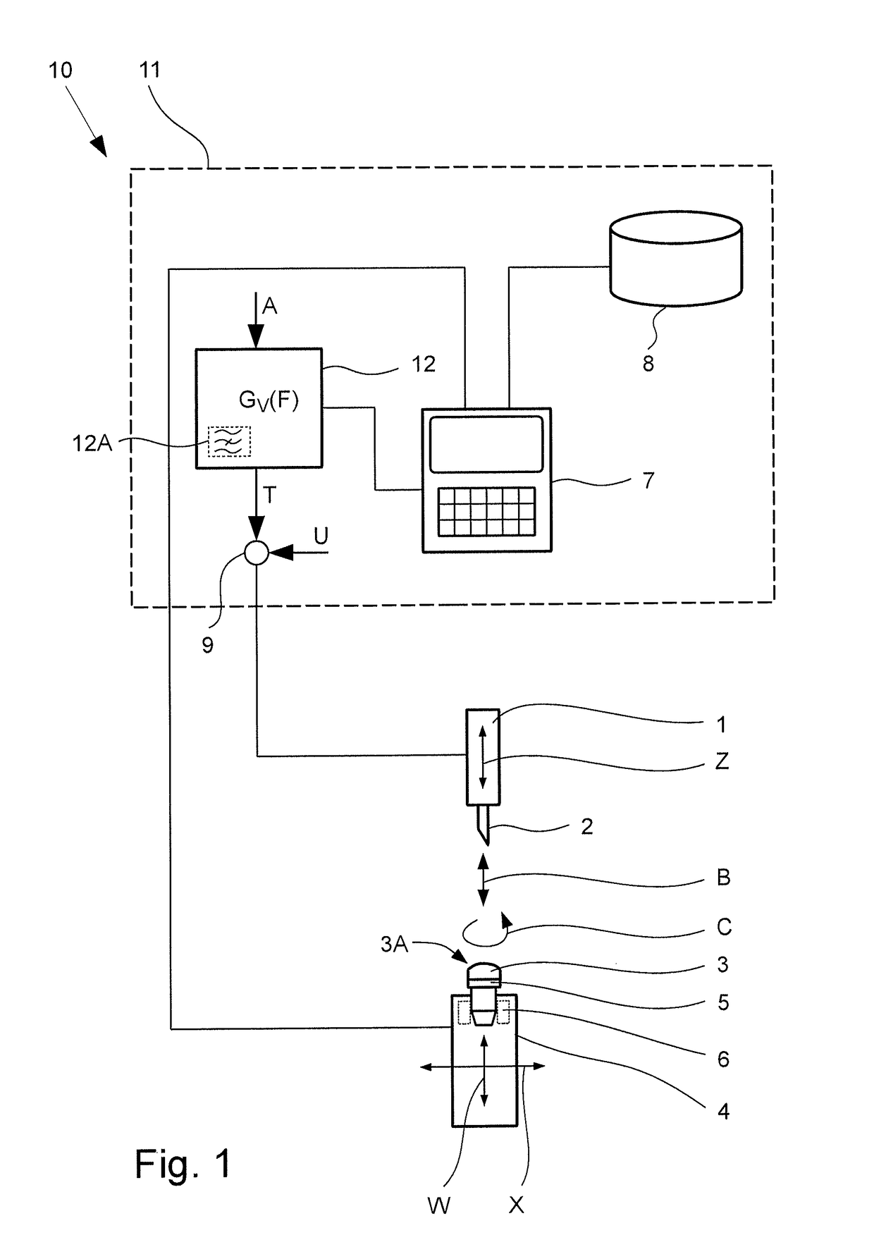
[0039]FIG. 1 shows a device 10 in accordance with the invention for cutting, preferably by turning, especially by face turning. The device 10 has preferably one drive 1 for driving or moving especially one assigned tool 2 or the like. Especially preferably the tool 2 is a machining tool, in the illustrated embodiment for machining of a workpiece 3.

[0040]The tool 2 for example, is made as a cutting tool, especially a turning tool or the like. Alternatively or in addition the tool 2 however can also be some other tool for machining, or a feeler, a measuring head, a sensor or the like.

[0041]In the illustrated example the tool 2 can be moved preferably linearly back and forth by means of the drive 1 or can be moved in a Z axis, especially for machining of the workpiece 3.

[0042]The drive 1 is for example, a servo, a highly dynamic motor or other actuator, especially the drive 1 is a complex, preferably electrically driven axle drive, such as a moving coil drive or the like, especially pr...


PUM


Abstract

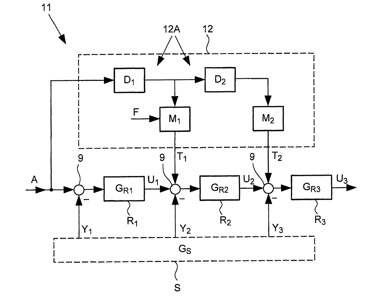
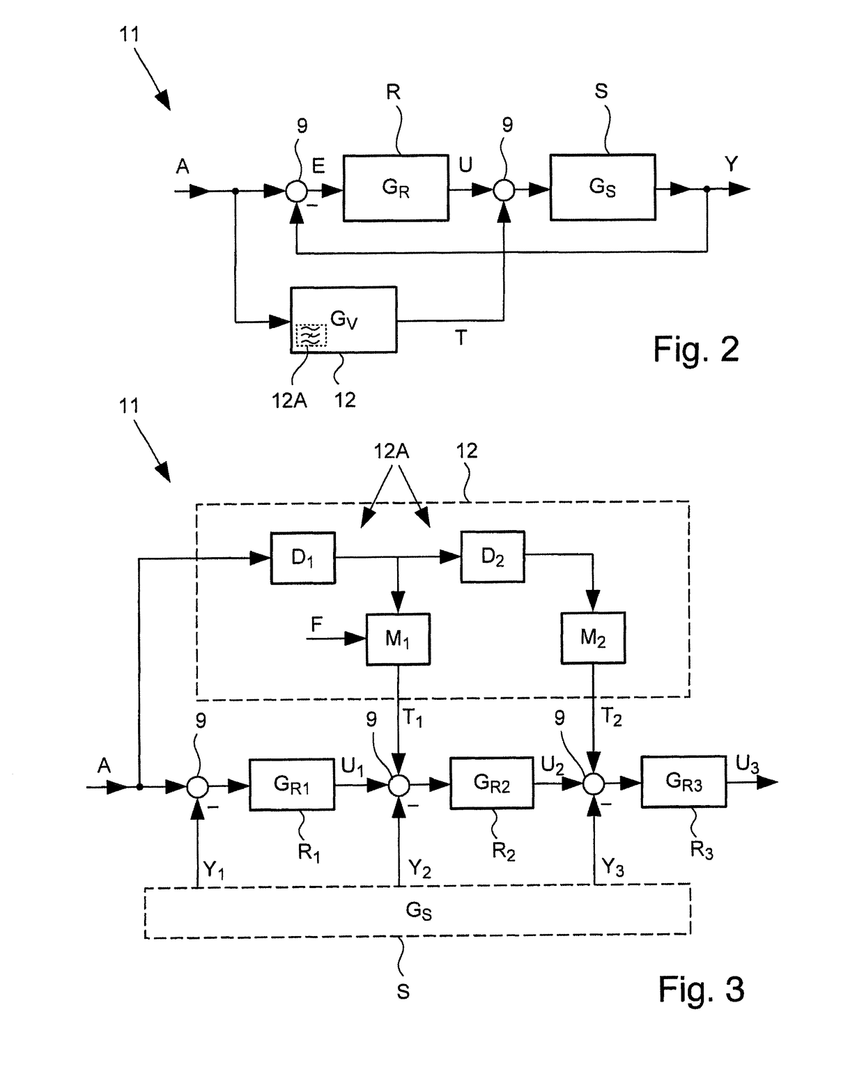
A method for control of a drive for a tool or workpiece uses pilot control and a device with a control apparatus, the pilot control taking place depending on a frequency of movement. At least one of a frequency component of the reference value, a spectrum of the reference value, and a part thereof is used as the frequency of movement. At least one pilot factor is determined depending on the frequency of movement, and the at least one determined pilot factor, multiplied with a pilot value that corresponds to or is a derivative of the reference variable is used for pilot control. In this way, a contouring error can be advantageously reduced.

Description

BACKGROUND OF THE INVENTION[0001]Field of the Invention[0002]This invention relates to a method for control of a drive for a tool or workpiece, especially for producing or machining an optical lens, in which pilot control takes place depending on a frequency of movement which corresponds to a reference variable and to a device with a control apparatus for controlling of a drive, especially for a tool or workpiece, especially preferably for machining of an optical lens, having a pilot control apparatus for pilot control of the drive depending on a frequency of movement which corresponds to a reference variable.[0003]Description of Related Art[0004]Fast and efficient machining of a workpiece with a tool requires a correspondingly fast and exact tool movement. In industrial fabrication, generally so-called “computerized numerical controls” (CNC) are generally used for exact positioning of tools, there being controls of the corresponding drives.[0005]Promptly reaching a target position ...

Claims


Application Information

Patent Timeline
Patent Type & Authority Patents(United States)
IPC IPC(8): G06F19/00G05B13/02G05B19/19G05B19/18G05B19/404
CPCG05B19/19G05B13/024G05B19/404G05B2219/49354
Inventor SCHNEIDER, GUNTERKLEIN, CHRISTOPH
Owner SCHNEIDER GMBH & CO KG
Learn More