

Transparent solar-heat collecting apparatus, solar water heating system, and solar cogeneration system
a solar water heating and collecting device technology, applied in thermal-pv hybrid energy generation, heating types, instruments, etc., can solve the problems of difficult to increase the size, and limited installation places of the devices, so as to reduce the weight of the solar water heating device, reduce the weight, and reduce the water depth in the conventional solar system
- Summary
- Abstract
- Description
- Claims
- Application Information
AI Technical Summary
Benefits of technology
Problems solved by technology
Method used
Image

Examples
embodiment 1
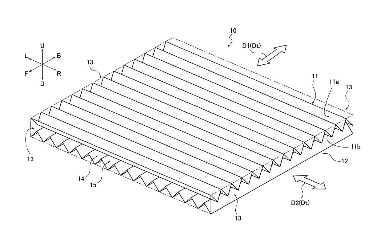
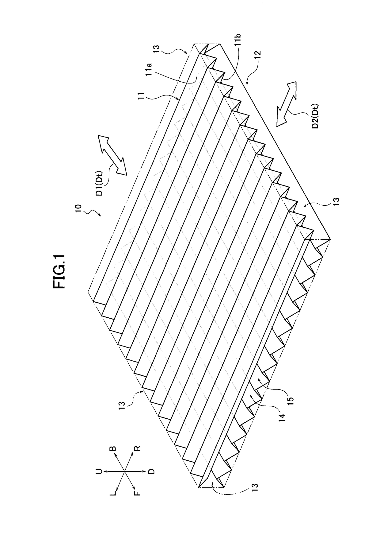
[0096]Here, a transparent solar heat absorbing apparatus 10A and a solar water heating system 30 equipped with the apparatus 10A according to a first embodiment of the present invention will be explained. Note that the same components of the apparatus 10A as those of the apparatus 10 are indicated by the same reference signs, and the detailed explanation thereof will be omitted. FIG. 12 is an explanatory view similar to FIG. 1 but for explaining the configuration of the apparatus 10A. FIG. 13 is an explanatory view for explaining the configurations of the solar water heating system 30.
[0097]As illustrated in FIG. 12, the apparatus 10A includes a transparent member 11, a wavelength selective member 12A, and side wall plates 13A. Additionally, the apparatus 10A further includes a bottom plate 16, an inlet 17, and an outlet 18. A transmission range (a predetermined wavelength range) of the wavelength selective member 12A is set to be shorter than 760 nm, and a reflection range (a presc...
embodiment 2
[0132]Next, a transparent solar heat absorbing apparatus 10 and a solar cogeneration system 50 equipped with the apparatus 10B according to a second embodiment of the present invention will be explained. Note that the same components of the apparatus 10B as those of the apparatus 10A are indicated by the same reference signs, and the detailed explanation thereof will be omitted. FIG. 15 is an explanatory view for explaining the configuration of the solar cogeneration system 50. FIG. 16 is a schematic view illustrating a multiple-reflection device 70 used to evaluate an influence of multiple reflections between a transparent member and a wavelength selective member of the apparatus 10B. FIG. 17A is a schematic view illustrating a first pattern (pattern 1) of a transparent member 11P1 and a wavelength selective member 12P1 of the multiple-reflection evaluator 70. FIG. 17B is a schematic view illustrating a second pattern (pattern 2) of a transparent member 11P2 and a wavelength select...
embodiment 3
[0167]Next, a transparent solar heat absorbing apparatus 10C and a solar water heating system 60 equipped with the apparatus 10C according to a third embodiment of the present invention will be explained. Note that the same components of the apparatus 10C as those of the apparatus 10A are indicated by the same reference signs, and the detailed explanation thereof will be omitted. FIG. 18 is an explanatory view illustrating the configuration of the solar water heating system 60. FIG. 19 is a partial enlarged view illustrating a preheater 98 and a heater 99 of the solar water heating system 60. FIG. 20 is an explanatory view illustrating examples for controlling temperature of water outputted from the solar water heating system of the third embodiment.
[0168]As illustrated in FIG. 18, the apparatus 10C of the solar water heating system 60 is connected with a first small-sized pump 61, a low-temperature heating medium tank 62, an electromagnetic valve 63, a first temperature sensor 64, ...
PUM
 Abstract
Description
Claims
Application Information