Roll stand changing device

a technology of changing device and roll stand, which is applied in the field of rolling mills, can solve the problems of inability to pull individual roll stand, inaccessible rolling line, and high design cost, and achieve the effect of changing individual roll stand in a short amount of tim

Active Publication Date: 2017-10-10
KOCKS TECH GMBH & CO
View PDF28 Cites 0 Cited by
  • Summary
  • Abstract
  • Description
  • Claims
  • Application Information

AI Technical Summary

Benefits of technology

[0013]The object of the invention is to create a device and a method for moving a roll stand into or out of a roll stand receptacle of a rolling line, as well as a system for moving a roll stand into or out of a roll stand receptacle of a rolling line, which functions reliably and which makes it possible to change the roll stands individually in a short amount of time. The ability to change roll stands individually or collectively (simultaneously) is desirable. In addition, the ability to move the roll stand changing carts both parallel to the rolling line, and also (insofar as desired) directly, i.e. out from the rolling block, transverse to the rolling line, into the roll stand workshop, is desirable.

Problems solved by technology

In the case of this group of roll stand changing devices, it is not possible to pull individual roll stands out of the rolling line while the remaining roll stands remain in the rolling line.
This design is very costly and in addition, the rolling line is generally inaccessible, which is a great disadvantage with regard to serviceability.
The configuration of the displacement mechanisms on the drive side has the disadvantage that the available installation space is extremely limited due to other components that are disposed here, as a result of which the displacement path that must be achieved is very small.
In addition, any maintenance work that is needed is costly and inconvenient to perform.
This can lead to serious disadvantages, which are dependent on the existing layout of the respective roll train.
In this case, this results in the disadvantage that at least twice the number of the roll stand displacement mechanisms must be provided, since there are always at least two roll stand changing carts present.
The result of this is that, for technical reasons, it is not possible to dispose the changing beam on the drive side, since, as a result, the roll stands cannot be moved individually, but rather, can only be moved collectively on the rolling block.
The result is the already known disadvantage that the roll stand changing cart cannot travel directly with the roll stands (transverse to the rolling line) into the roll stand workshop.
This design has the disadvantage that two roll stand displacement units must be provided, since at least two roll stand changing carts are needed in order to quickly exchange a roll stand.
The disadvantage, however, is that the displacement unit must make a number of empty trips in order to connect to the changing beam located on the roll stand changing cart before displacing the roll stand, and in order to disconnect from the changing beam and return to the starting position after the displacement of the roll stand.
Furthermore, the required coupling mechanism results in a cost disadvantage.
The primary disadvantage of this so-called tunnel solution is that a displaceable roller table must be disposed either in front of or behind the rolling block, in order to create the space to move the device out of the rolling block.
Under circumstances, this results in serious disadvantages for the layout of the entire roll train.
This increases the technical complexity however, without reducing the overall space requirements.

Method used


Image

  • Roll stand changing device
  • Roll stand changing device
  • Roll stand changing device

Examples


Embodiment Construction

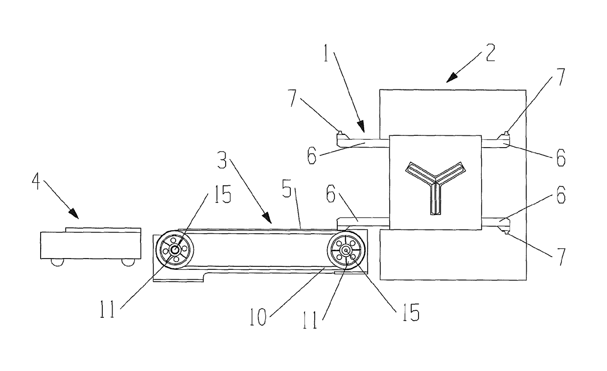
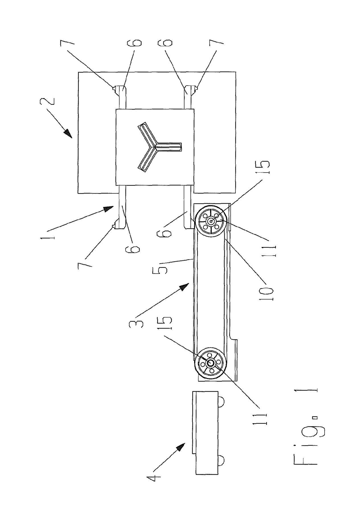
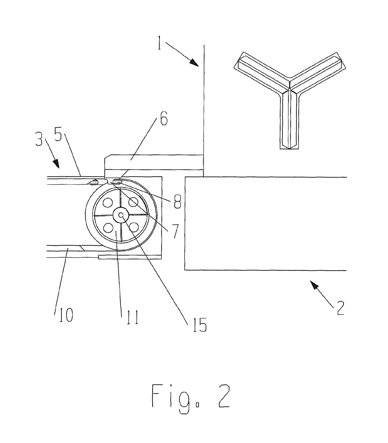
[0023]The core idea of the invention is to provide at least one carrier element, which is moved along a predetermined curved path by means of a conveying element. The curved path has at least one non-linear (non-translational) section, along which the carrier element is moved along a curve, and thus, not along a linear path.

[0024]The carrier element performs a predetermined movement that is imparted thereto by the conveying element, which movement makes it possible to quickly connect to and disconnect from the entrainment element of the roll stand, for example. In particular, the movement of the carrier element along the curved path may be configured in such a way that it includes a reciprocating motion transverse to the rolling line, and is combined with a movement along a curve, for example with a lowering and / or raising movement. The reciprocating motion may be a pure translational movement, which may be followed by the curved movement, for example a lowering and / or raising movem...


PUM

PropertyMeasurementUnit
angleaaaaaaaaaa
angleaaaaaaaaaa
angleaaaaaaaaaa

Abstract

The invention relates to a device for moving a roll stand into or out of a roll stand receptacle of a rolling line, comprising a carrier element for entraining an entrainment element of a roll stand and a conveying element, wherein the carrier element is moved along a predetermined curved path.

Description

CROSS REFERENCE TO RELATED APPLICATIONS[0001]This application claims the benefit under 35 U.S.C. §119(a) or German Patent Application No. 102014004637.0, filed Apr. 1, 2014, the entire disclosure of which is incorporated herein by reference in its entirety for all purposes.FIELD OF THE INVENTION[0002]This disclosure relates to rolling mills. In particular, this disclosure relates to changing roll stands in a rolling mill.BACKGROUND OF THE INVENTION[0003]Roll stands having a plurality of rolls, which are designed and disposed such that they form a roll pass for rolling rod-shaped or tubular shaped rolling material, are known in multiple designs. The roll stands are disposed in a roll stand receptacle in a rolling line. Changes in the dimensions of the rolled product or a change of the rolls as a result of damage or wear makes it necessary to change one or a plurality of roll stands and to replace those stands with others.[0004]Previously known roll stand changing devices can essentia...

Claims


Application Information

Patent Timeline
Patent Type & Authority Patents(United States)
IPC IPC(8): B21B31/08B21B31/10B21B13/10
CPCB21B31/08B21B31/103B21B13/10B21B13/103
Inventor POTTHOFF, HEINRICH
Owner KOCKS TECH GMBH & CO
Why Eureka
Try Eureka