Device for vacuum processing

a vacuum processing and device technology, applied in the field of vacuum processing devices, can solve the problems of hindering temperature increase, heat induction system, difficult to heat a substrate to 1000° c. or higher, etc., and achieve the effect of changing the substrate temperature in a short tim

Inactive Publication Date: 2013-02-19
NAT INST FOR MATERIALS SCI
View PDF6 Cites 0 Cited by
  • Summary
  • Abstract
  • Description
  • Claims
  • Application Information

AI Technical Summary

Benefits of technology

[0008]In the present invention, the laser beam in linear space does not come into contact with the thin film or vapor occupying other parts in the chamber. Accordingly, the laser beam reaches the substrate without being attenuated. This makes it possible to change the substrate temperature in a short time during thin film deposition using, for example, the CVD method. Furthermore, the substrate can be stably heated to as high as 1500° C. or higher (for example) for a long time.

Problems solved by technology

However, this conventional method has problems that make it difficult to heat a substrate to 1000° C. or higher.
Sample problems that hinder temperature increase include heater disconnections or film adhesion and formation on the condenser lens used for the lamp (particularly in processes such as CVD that require high pressure).
However, since the carbon heater itself is highly susceptible to oxidation and a reducing atmosphere, the surface of the carbon heater must be coated with an atmosphere-resistant substance such as BN.
On the other hand, the heat induction system has other problems, such as an inability to use a metal chamber, complicated substrate conveyance, and low degree of design freedom.
However, even though the laser heater guides the laser beam is guided to an area near a substrate by means of an optical fiber, a thin film also adheres to the end face of the fiber during the thin film deposition process, such as the CVD method, which requires a relatively high pressure (several mTorr or higher) since the end face of the optical fiber is exposed in a thin-film forming device.
As a result, the laser output and hence temperature decreases and the laser body is damaged by the reflected light.

Method used


Image

  • Device for vacuum processing
  • Device for vacuum processing

Examples


Embodiment Construction

[0029]One embodiment of the present invention will hereinafter be described. Of course, the invention is not limited thereto.

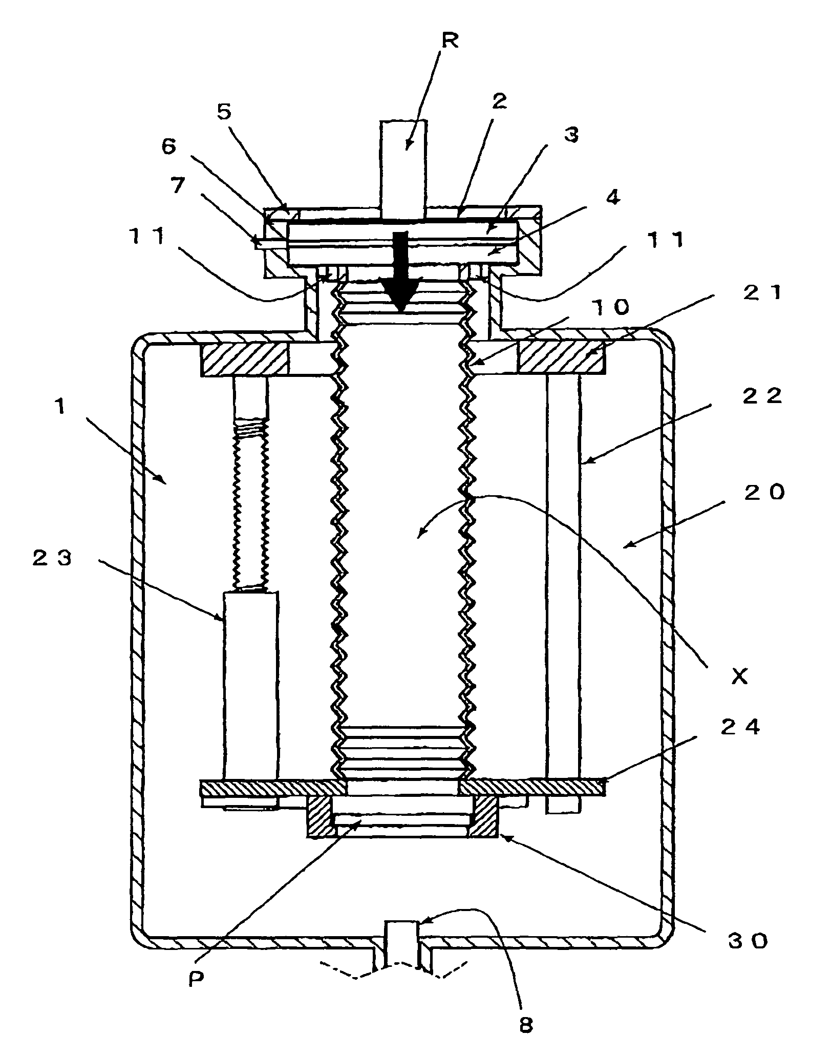
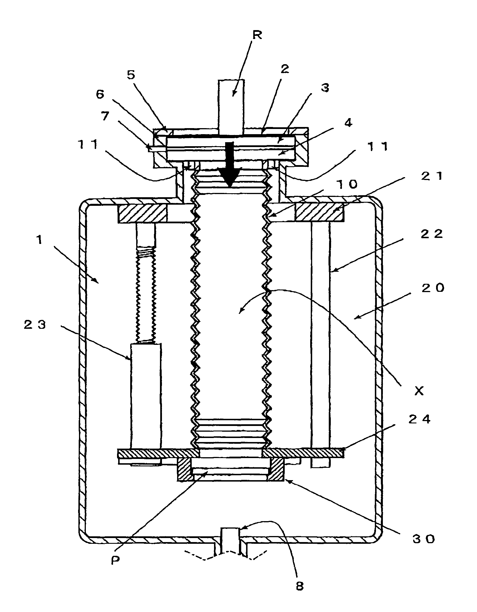
[0030]FIG. 1 is a vertical view showing an embodiment of a device for vacuum processing in the present invention.

[0031]A vacuum chamber (1) has a light transmissible window (6) at the top. The light transmissible window (6) is fixed by a fixing flange (5) so that a space having an anti-fog gas inlet (7) is left between upper and lower reinforcement glass plates (3) and (4). An anti-reflection film (2) is formed on the upper face of the upper reinforcement glass (3).

[0032]A high output semiconductor laser emitter (R) of collimation type is installed above the upper reinforcement glass (3) so that the direction of emission is oriented downward (indicated by the black arrow in FIG. 1).

[0033]A substrate raising / lowering device (20) in the vacuum chamber (1) is configured such that an upper frame (21) fixed to the upper part of the vacuum chamber (1) and a lower fr...


PUM

PropertyMeasurementUnit
temperaturesaaaaaaaaaa
temperatureaaaaaaaaaa

Abstract

Disclosed is a device for vacuum processing that performs vapor-deposition on a substrate being heated in a vacuum chamber; the device, wherein the chamber has a light transmissible window formed in a section of the chamber; the light transmissible window and a holding part holding the substrate are connected by a linear space isolated from other parts in the chamber; a laser emitter is installed outside the light transmissible window; and the laser emitter emits a laser beam to the substrate through the linear space, thereby heating the substrate. This device enables laser heating, eliminating conventional drawbacks such as a decrease in laser output.

Description

TECHNICAL FIELD[0001]The present invention relates to devices for vacuum processing that perform vapor-deposition on a substrate being heated in a vacuum chamber. In particular, the invention relates to devices for vacuum processing characterized by a heating system optimal for a process that requires growth using AlN, BN, or bulk Si at high temperatures or for a thin film growth process that requires a speedy change in the substrate temperature, as in making a ZnO thin film p-type.BACKGROUND ART[0002]Conventionally, temperature is an important parameter in material development. In vacuum processing of vapor-deposition performance on a substrate being heated, an approach in which the light of a heater is condensed using a heating wire or an infrared lamp is generally employed for heating. However, this conventional method has problems that make it difficult to heat a substrate to 1000° C. or higher. Sample problems that hinder temperature increase include heater disconnections or fi...

Claims


Application Information

Patent Timeline
Patent Type & Authority Patents(United States)
IPC IPC(8): C23C16/00
CPCC23C16/481
Inventor SUMIYA, MASATOMOLIPPMAA, MIKKOHNISHI, TSUYOSHIFUJIMOTO, EIJIKOINUMA, HIDEOMI
Owner NAT INST FOR MATERIALS SCI
Why Eureka
Try Eureka