Machine tool and machine tool system

a machine tool and tool system technology, applied in the field of multi-axis processing machines, can solve the problems of inability to perform inverting operation, inability to change the pallet period, failure of slow inverting operation, etc., and achieve the effect of shortening the processing period of the workpiece, and easy processing

Active Publication Date: 2021-02-02
OKUMA CORP
View PDF11 Cites 0 Cited by
  • Summary
  • Abstract
  • Description
  • Claims
  • Application Information

AI Technical Summary

Benefits of technology

[0015]With the machine tool according to the embodiment, a stroke to cause the workpiece loading and unloading device to access to the table to place the workpiece on can be shortened, thereby ensuring changing the workpiece in a considerably short period. When similar machine tools are disposed on the right and left, the workpiece is delivered to an adjacent machine tool. Therefore, steps can be divided by the machine tool, thereby ensuring shortening a processing period per one step. Moreover, the workpiece can be inverted in a short period to ensure easily performing processing on the installation surface of the workpiece with the table.
[0016]The machine tool systems according to the second to fourth aspects cause the loading and unloading devices to simultaneously access from two directions among the right and left and the front of the machine tool for changing the workpiece in an extremely short period, thereby ensuring the substantially short processing period of the workpiece.

Problems solved by technology

However, when the pallet changer is mounted to a five-axis machine, a necessity of an avoidance operation of one axis that is not required in a horizontal machining center is increased, and therefore, a changing period of the pallet takes long.
When processing is performed on all surfaces of the workpiece, even the five-axis machine cannot perform processing on an installation surface of the workpiece with the table.
However, when an inverting mechanism is mounted in the workpiece loading and unloading device, a driving device of the inverting mechanism has to be small, thereby leading to a failure of a slow inverting operation.
Therefore, an access can be made only from a certain direction, thereby leading to a failure of a limited layout for installation.

Method used


Image

  • Machine tool and machine tool system
  • Machine tool and machine tool system
  • Machine tool and machine tool system

Examples


Embodiment Construction

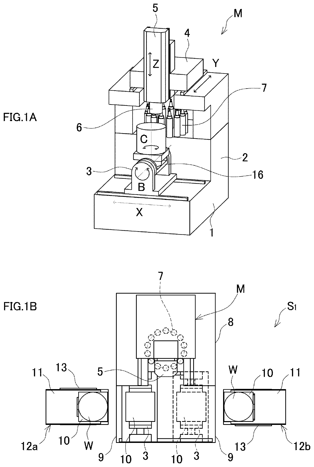
[0023]The following describes one embodiment of a machine tool and a machine tool system according to the disclosure in details based on drawings. FIGS. 1A and 1B illustrate a machine tool and a machine tool system using the machine tool according to the disclosure. FIGS. 2A to 2D illustrate operation contents of the machine tool system. A machine tool system S1 is constituted of a machine tool M, a cover 8 covering the machine tool M, and two workpiece loading and unloading devices 12a, 12b installed in a peripheral area of the machine tool M (the two workpiece loading and unloading devices 12a, 12b have identical structures).

[0024]In the machine tool M, a bed 1 that serves as a base is disposed to be in a rectangular parallelepiped shape. In a back side of the bed 1, a column 2 in a vertically-elongated rectangular parallelepiped shape is consecutively installed. Furthermore, in a front of the column 2, a trunnion unit 3 in an approximately U-shape from a side view is disposed mov...


PUM

PropertyMeasurementUnit
heightaaaaaaaaaa
widthaaaaaaaaaa
distanceaaaaaaaaaa

Abstract

A machine tool includes a base, a table, a main spindle, and a trunnion unit. The table is installed on the base. A tool is mounted to the main spindle. The main spindle is caused to approach a workpiece on the table along an up-down direction. The trunnion unit is configured to rotatably hold the table on which the workpiece is placed using a rotation axis along a front-rear direction as a center. The trunnion unit is disposed movable in a right-left direction.

Description

BACKGROUND[0001]This application claims the benefit of Japanese Patent Application Numbers 2016-206296 filed on Oct. 20, 2016 and 2016-223490 filed on Nov. 16, 2016, the entirety of which is incorporated by reference.TECHNICAL FIELD[0002]The disclosure relates to a machine tool for multi-axis processing, such as a machining center, and a machine tool system including the machine tool and peripheral devices.RELATED ART[0003]When workpiece processing is automated in a machining center, operations of conveying and attaching / removing the workpiece are necessary between machines used in each of steps. These operations of conveying and attaching / removing the workpiece are usually performed by a pallet changer, a loader, or a workpiece loading and unloading device like an articulated or linear-type / rotary-type robot.[0004]As a machine tool including such a workpiece loading and unloading device, Japanese Patent No. 5328782 discloses a machine tool that includes a pallet changing means in o...

Claims


Application Information

Patent Timeline
Patent Type & Authority Patents(United States)
IPC IPC(8): B23Q7/14B23Q1/48B23Q1/01B23Q1/28B23Q39/04B23C1/08B23Q41/02B23Q3/157
CPCB23Q7/1463B23C1/08B23Q1/4857B23Q39/048B23Q41/02B23Q1/015B23Q1/28B23Q3/15766B23Q7/1494Y10T29/5124Y10T29/5196Y10T408/5614Y10T409/30532Y10T409/30896Y10T409/305264Y10T409/305768Y10T409/305824Y10T409/307168Y10T483/165Y10T483/1795B23Q3/155B23Q7/00B23Q11/08
Inventor TSUCHIDA, KOJI
Owner OKUMA CORP
Why Eureka
Try Eureka