Firewall rule management

a technology of rule management and firewall, applied in the direction of electrical equipment, transmission, software simulation/interpretation/emulation, etc., can solve the problems of behavior (e.g., cannot be easily changed dynamically, and the location of the rule is not easy to chang

Active Publication Date: 2017-10-10
NICIRA
View PDF6 Cites 31 Cited by
  • Summary
  • Abstract
  • Description
  • Claims
  • Application Information

AI Technical Summary

Benefits of technology

[0005]In some embodiments, this interface provides robust controls for granularly defining the enforcement points (e.g., the ports) at which the firewall rule sets are applied. The interface in some embodiments allows a user to specify a set of enforcement points in a firewall rule definition along with the standard data tuples (e.g., source IP, destination IP, source port, destination port, and protocol) that are used to match the firewall rule to the packet header attributes. In other words, to provide the ability to specify a set of enforcement nodes in the network at which a particular firewall should be enforced, the management interface of some embodiments adds an extra tuple (referred to below as the AppliedTo tuple) to a firewall rule. This added AppliedTo tuple can specify the set of enforcement points at which the firewall rule has to be applied (i.e., enforced).

Problems solved by technology

While conventional firewalls provide a means to filter the traffic going through them, their location (e.g., perimeter versus port) and behavior (e.g., simple packet filtering, proxy server, stateful firewall, and deep packet inspection) cannot be easily be changed dynamically, in order to ensure that all traffic pass through them.
Moreover, existing firewall solutions lack adequate controls for identifying in a granular fashion the different sets of ports that are to be assigned the different sets of firewall rules.
This problem becomes worse when different enforcements schemes are utilized, such as enforcement rules that restrict east-west traffic (e.g., L3 firewall rules that restrict routing within the datacenter) and north-south traffic (e.g., L3 firewall rules that restrict traffic coming into or going out of the datacenter).
This problem is especially acute when third party vendor solutions with different management interfaces are used to define these different enforcement schemes.

Method used


Image

  • Firewall rule management
  • Firewall rule management
  • Firewall rule management

Examples


Embodiment Construction

[0029]In the following detailed description of the invention, numerous details, examples, and embodiments of the invention are set forth and described. However, it will be clear and apparent to one skilled in the art that the invention is not limited to the embodiments set forth and that the invention may be practiced without some of the specific details and examples discussed.

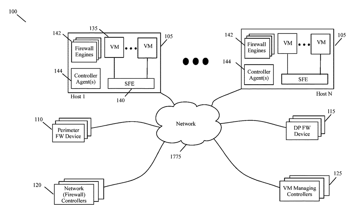
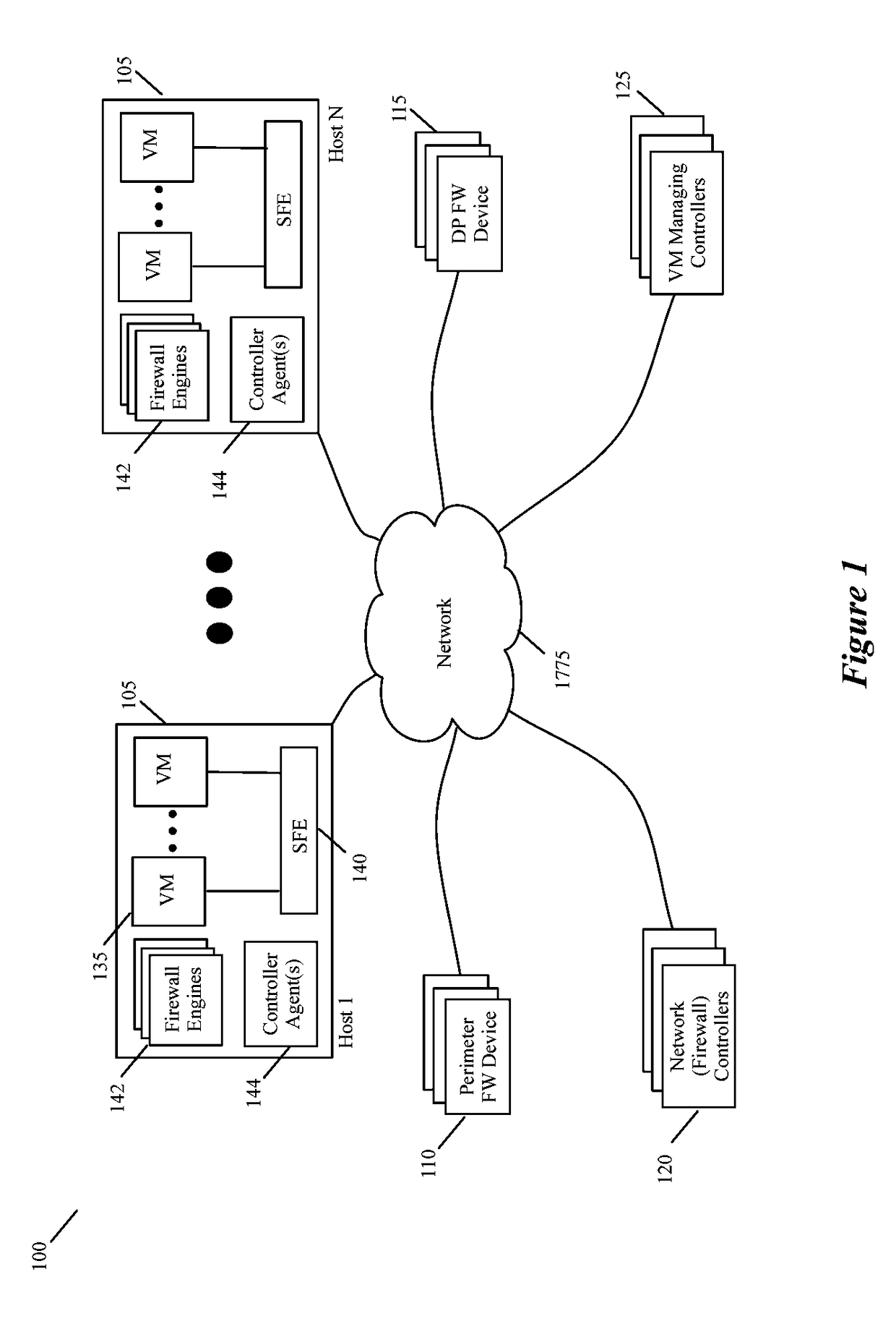
[0030]Some embodiments provide a central firewall management system that can be used to manage different firewall engines with different rule sets on different enforcement points from a single management console. This management console is a uniform management interface for defining different firewall rule sets (e.g., for different tenants, for different networks, for different sub-networks of the same tenant, etc.) and deploying these rules sets on different firewall devices. The firewall devices can differ as to their type (e.g., port-linked firewall engines, firewall service VMs (SVMs), network-perimeter fi...


PUM


Abstract

Some embodiments provide a central firewall management system that can be used to manage different firewall devices from a single management interface. This management interface provides a uniform interface for defining different firewall rule sets and deploying these rules sets on different firewall devices (e.g., port-linked firewall engines, firewall service VMs, network-perimeter firewall devices, etc.). Also, this interface allows the location and / or behavior of the firewall rule sets to be dynamically modified. The management interface in some embodiments also provides controls for filtering and debugging firewall rules.

Description

BACKGROUND[0001]Forwarding elements in a network typically enforce permissive rules that specify how the traffic in network should flow. On the other hand, firewall rules in the network define the type of traffic that can flow through the network. Today, networks typically enforce firewall rules by using one or more hardware appliances and / or software firewall engines, such as service virtual machines (VMs) or firewall engines linked to software ports on host computers.[0002]With logical networking space increasing drastically in software-defined datacenters, demand for traffic filtering via firewalls is increasing. While conventional firewalls provide a means to filter the traffic going through them, their location (e.g., perimeter versus port) and behavior (e.g., simple packet filtering, proxy server, stateful firewall, and deep packet inspection) cannot be easily be changed dynamically, in order to ensure that all traffic pass through them.[0003]Moreover, existing firewall soluti...

Claims


Application Information

Patent Timeline
Patent Type & Authority Patents(United States)
IPC IPC(8): H04L29/06G06F9/455
CPCH04L63/0263H04L63/0218G06F9/455
Inventor BANSAL, KAUSHALMASUREKAR, UDAYMASKALIK, SERGESHAH, SHADABSRINIVASAN, ARAVINDAGARWAL, MINJAL
Owner NICIRA
Why Eureka
Try Eureka