Lighting device and illumination apparatus using same

a technology of illumination apparatus and light source, which is applied in the direction of fixed installation, light source combination, instruments, etc., can solve the problems of excessive inrush current flow, led group turning, and switching element stress, so as to reduce the stress on semiconductor light emitting elements or light source switches included in series load circuits, avoid the greatest difference in voltage drop, and reduce the effect of voltage drop

Inactive Publication Date: 2017-10-10
PANASONIC INTELLECTUAL PROPERTY MANAGEMENT CO LTD
View PDF22 Cites 3 Cited by
  • Summary
  • Abstract
  • Description
  • Claims
  • Application Information

AI Technical Summary

Benefits of technology

[0010]In view of the above, the present disclosure provides an illumination apparatus and a lighting device for lighting a plurality of light sources to emit lights of different colors in a time-divisional manner so that stress to semiconductor light emitting elements and / or switching elements can be suppressed and an excessive current can be prevented from flowing the light sources.
[0046]Accordingly, stress exerted to a semiconductor light emitting element or a light source switch included in the series load circuit can be reduced.
[0047]Additionally, in accordance with the above aspects of the present invention, for example, among the at least three light sources, switching from the light source switch connected to the light source of the relatively great voltage drop to the light source switch connected to the light source of the relatively small voltage drop can be avoided. Further, the switching causing the greatest difference in voltage drops can be avoided. Accordingly, the greatest inrush current possibly occurring in series load circuits can be avoided and excessive inrush current can be suppressed. As a result, damage and stress to the light sources and the light source switches can be relieved, and the lifespan of the lighting device can be prolonged.
[0048]In the repeated predetermined order of switching the light source switches, among switching from the light source switch connected to the light source of the relatively great voltage drop to the light source switch connected to the light source of the relatively small voltage drop, the greatest inrush current are likely to occur at the time of switching when the difference in voltage drops becomes greatest. In accordance with the aspects of the present invention, since inrush current suppression control is conducted at the switching where the greatest inrush currents are likely to occur, damage and stress to the light sources and the light source switches can be relieved, and the lifespan of the lighting device can be prolonged.

Problems solved by technology

However, the above-mentioned time-divisional manner, in which the LEDs are lit time-divisionally while adjusting the duty ratio, has problems in that, when a LED group to which a power is supplied is changed sequentially, the switching element may be under stress or an excessive inrush current may flow in a LED group which is turned on by the changing.
Therefore, when the LED group to which the power is supplied is changed sequentially, the excessive inrush current may flow in the LED group turned on.

Method used


Image

  • Lighting device and illumination apparatus using same
  • Lighting device and illumination apparatus using same
  • Lighting device and illumination apparatus using same

Examples


first embodiment

[0077](First Embodiment)

[0078]An illumination apparatus 100 in accordance with a first embodiment will be described with reference to FIGS. 1 to 4, and FIGS. 5A and 6A.

[0079](Overall Configuration of Illumination Apparatus 100)

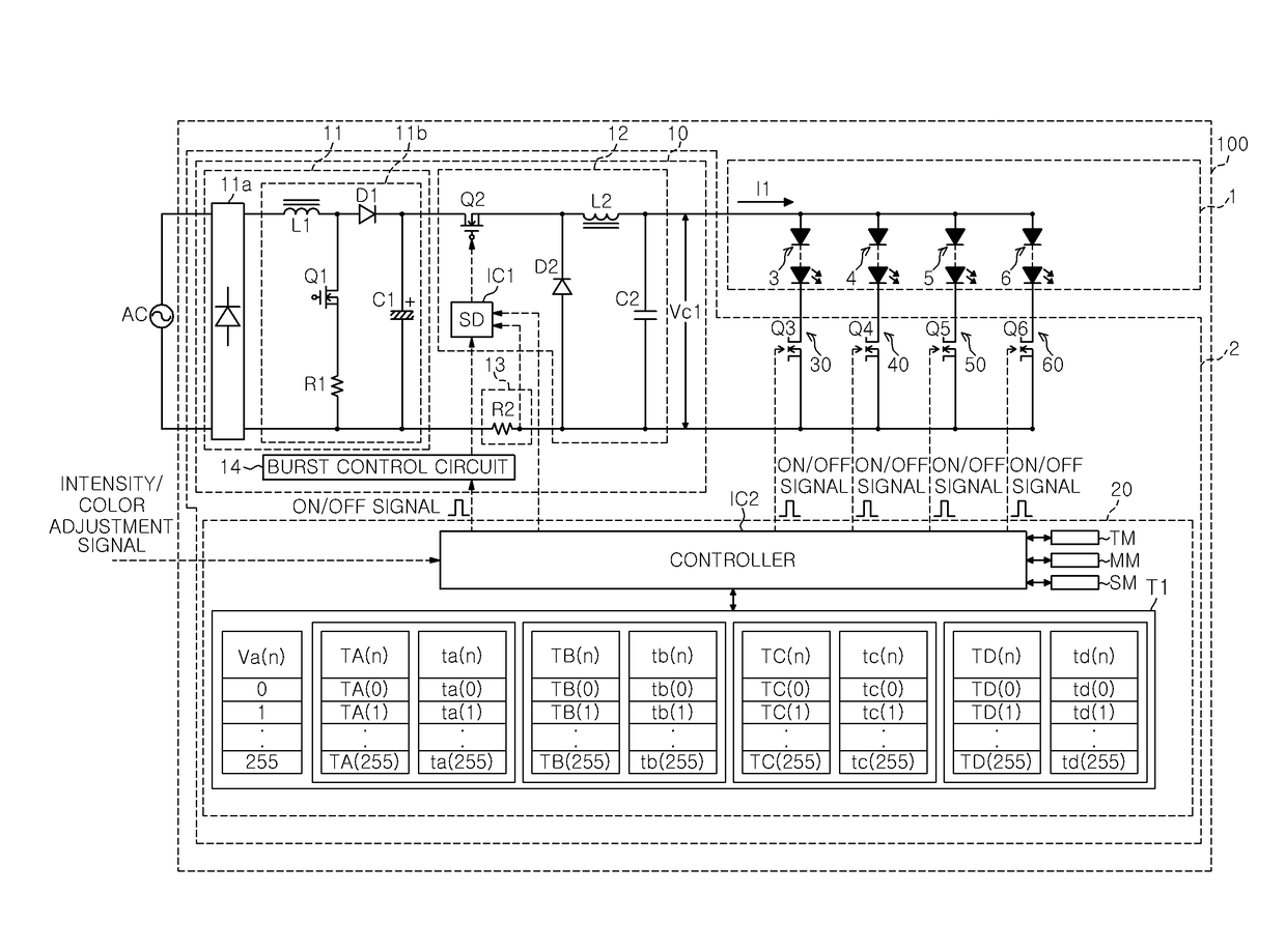
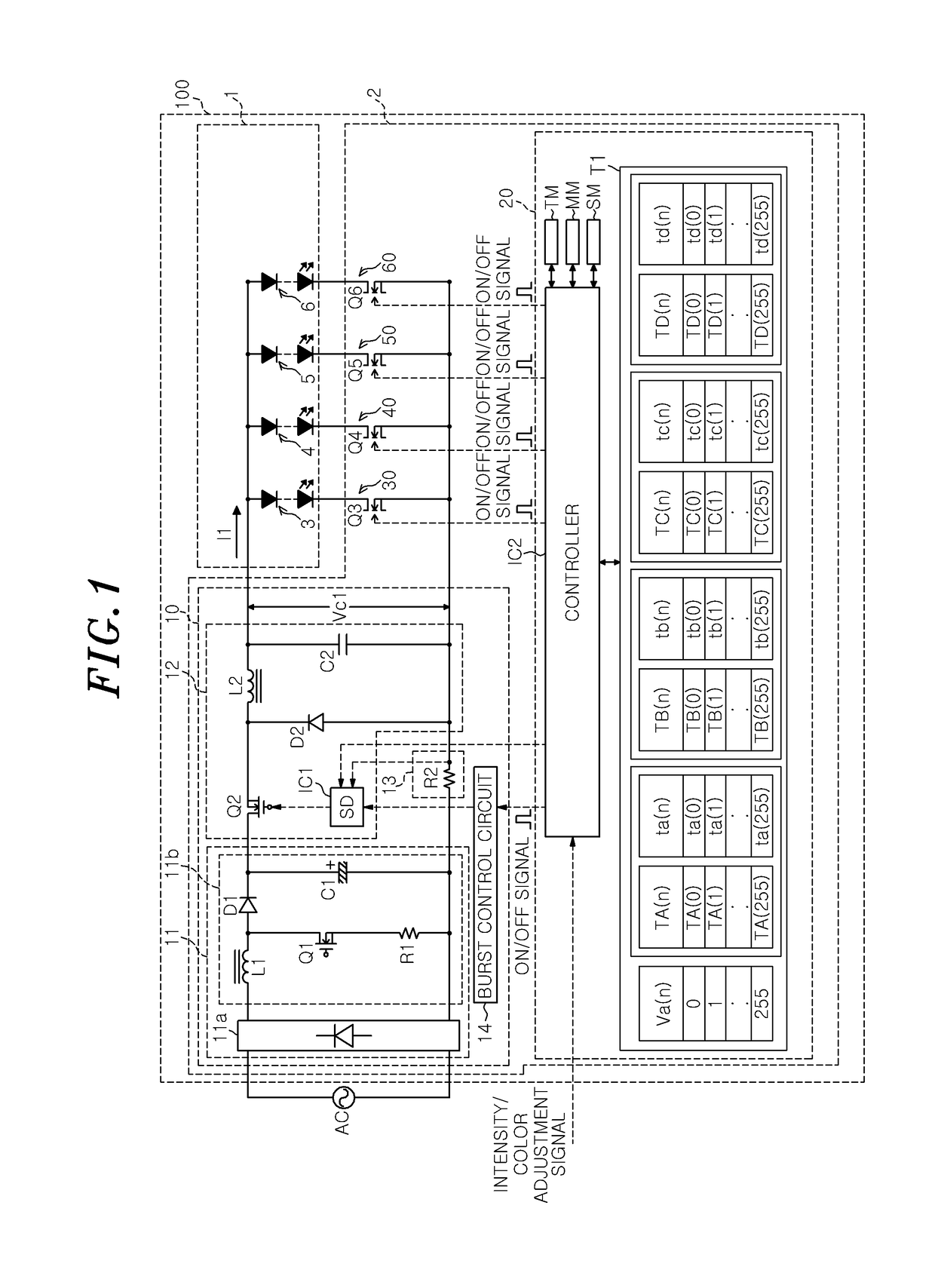
[0080]As illustrated in FIG. 1, the illumination apparatus 100 includes a light source unit 1 including a plurality of light sources including LED (Light Emitting Diode) groups 3 to 6 which emit lights of different colors, and a lighting device 2 to operate the LED groups 3 to 6 of the light source unit 1 by flowing a current through the LED groups 3 to 6. The colors of lights emitted from the LED groups 3 to 6 are, e.g., red (R), green (G), blue (B), white (W), respectively.

[0081]In the light source unit 1 shown in FIG. 1, each of the LED groups 3 to 6 includes LEDs connected in series which emit the same color and have the same characteristics. However, the LED groups 3 to 6 may include a single red LED, green LED, blue LED, and white LED, respectively.

[0082...

first modification

[0220](First Modification)

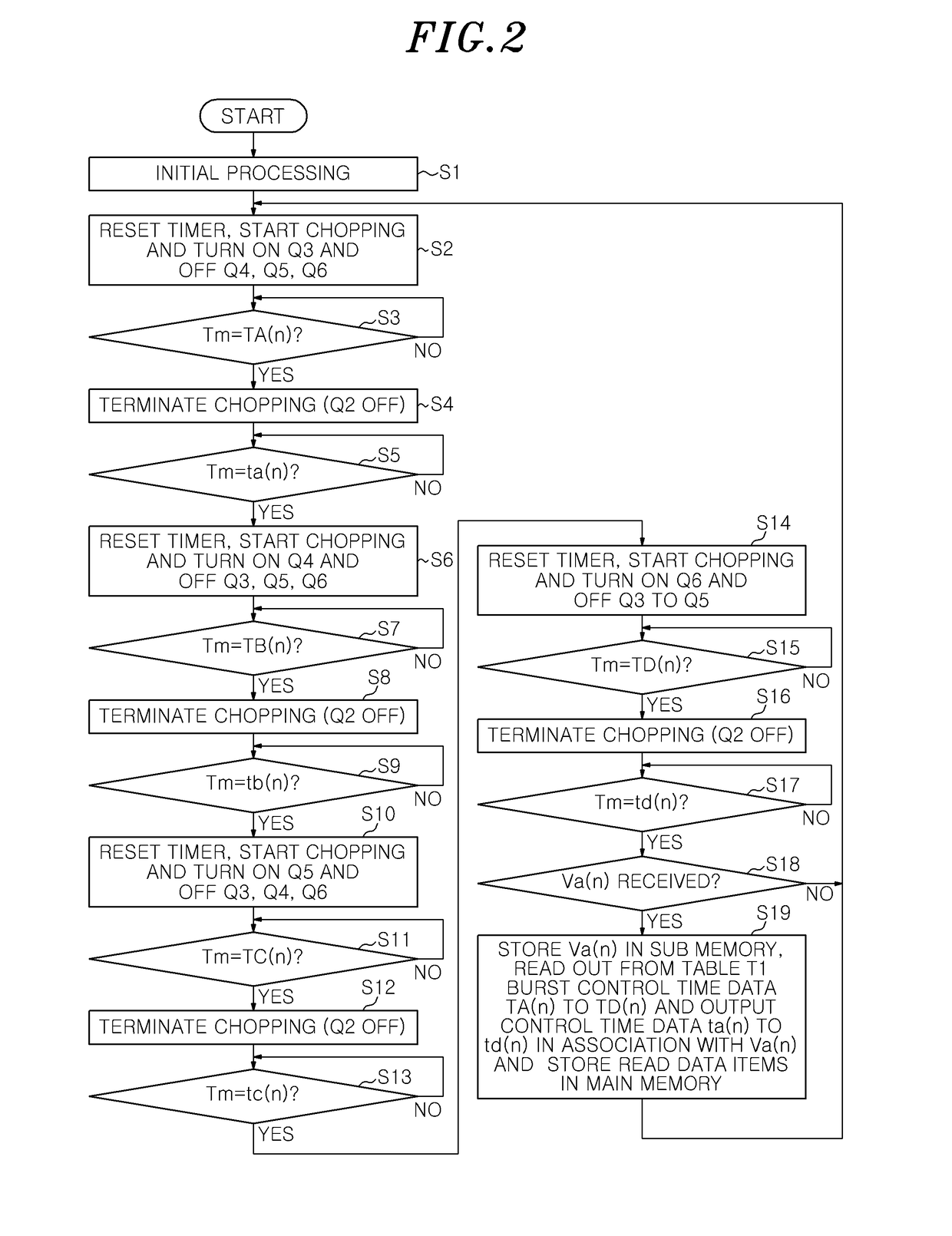
[0221]An illumination apparatus 100 in accordance with the first modification has the same configuration as the illumination apparatus 100 in accordance with the first embodiment shown in FIG. 1. Further, the control operations by the control unit 20 are also conducted based on the flowchart illustrated in FIG. 2. In addition, in order to avoid redundant descriptions, the same elements as in the first embodiment are denoted by the like numerals throughout the modifications and embodiments below and descriptions thereof will be omitted.

[0222]In the present modification, however, the control unit 20 stores therein a table T2 as shown in FIG. 5B to perform control operations based on the table T2.

[0223]As the illumination apparatus 100 in accordance with the first embodiment, the illumination apparatus 100 in accordance with the present modification reads from the table T2 the burst control time data TA(n), TB(n), TC(n) and TD(n) based on a number specified by...

second modification

[0232](Second Modification)

[0233]The illumination apparatus 100 in accordance with the second modification also has the same configuration as the illumination apparatus 100 in accordance with the first embodiment shown in FIG. 1. Further, control operations by the control unit 20 are conducted also based on the flowchart illustrated in FIG. 2.

[0234]In the present modification, however, the control unit 20 includes a table T3 shown in FIG. 5C to perform the control operations based on the table T3.

[0235]As the illumination apparatus 100 in accordance with the first embodiment, the illumination apparatus 100 in accordance with the present modification reads from the table T3 the output control time data ta(n), tb(n), tc(n) and td(n) based on a number specified by the intensity / color adjustment signal data Va(n), and the light source switches Q3 to Q6 are switched over based on the output control time data ta(n), tb(n), tc(n) and td(n).

[0236]However, in the illumination apparatus 100 i...


PUM


Abstract

A lighting device includes: a DC power source circuit; an output control circuit including a chopping switch to adjust an output current by chopping of the chopping switch; light source switches respectively connected to the light sources; and a control unit for controlling a time period for which a current flows in the light sources. The control unit controls the output control circuit such that an operation period for which the chopping is conducted and a stop period for which the chopping is stopped are repeated alternately and performs switchover of the light source switches to be sequentially and selectively turned on, and the switchover is conducted during the stop period with a time interval from a beginning of the stop period.

Description

CROSS-REFERENCE TO RELATED APPLICATION[0001]This application claims priority to Japanese Patent Application Nos. 2013-246032, 2013-246033 and 2013-246034 filed on Nov. 28, 2013, the entire contents of which are incorporated herein by reference.TECHNICAL FIELD[0002]The present disclosure relates to a lighting device for lighting light sources of different colors to emit a light and to an illumination apparatus using the lighting device.BACKGROUND ART[0003]Recently, an illumination apparatus is used that includes a lighting device for lighting a light source unit having groups of semiconductor light emitting elements such as LEDs (Light Emitting Diodes) for emitting lights of different colors including green, blue, red or the like.[0004]In such an illumination apparatus, the chromaticity or intensity of a combined light emitted therefrom can be adjusted by adjusting the intensity of light emitted from each LED group.[0005]There is known a lighting device used in the illumination appar...

Claims


Application Information

Patent Timeline
Patent Type & Authority Patents(United States)
IPC IPC(8): G05F1/00H05B37/02H05B39/04H05B41/36H05B33/08F21S8/02F21S8/00H05B44/00F21Y101/00F21Y113/13F21Y115/10
CPCH05B33/0827H05B33/0815F21S8/026F21S8/038Y02B20/347F21Y2113/13F21Y2115/10H05B37/02Y02B20/346F21Y2101/00H05B45/46H05B45/38H05B47/165H05B45/375H05B45/24H05B47/25Y02B20/30
Inventor HASEGAWA, JUNICHIHIRAMATU, AKINORIIDO, SHIGERU
Owner PANASONIC INTELLECTUAL PROPERTY MANAGEMENT CO LTD
Why Eureka
Try Eureka