Container for actuating a drive device of the container

Inactive Publication Date: 2017-10-17
KESSEBOHMER HLDG KG
View PDF14 Cites 0 Cited by
  • Summary
  • Abstract
  • Description
  • Claims
  • Application Information

AI Technical Summary

Benefits of technology

[0004]The object of the present invention is to provide a container of the above named type, in which it is possible to realise that for actuating the drive device, an as small as possible path, which preferably is not noticeable for the user, can be achieved for actuating an actuating device.
[0007]This has the advantage, that assembly tolerances of the two element towards each other and the deformation measuring unit have no influence, when the drive device is actuated. Commonly used switching elements have a precise switching point, when reaching it or exceeding it, the switch is switched from one condition to another condition. Thus, it is clearly set, in which position of the switching element the drive device is actuated. The position of this switching point depends on the assembly tolerances. Especially then, when the drive device is actuated by a force exerted on an element of the container, i.e. the switching element is switched indirectly, e.g. via a flap of the container, the switching point is pre-set by the assembly tolerances. This is not the case, when using a deformation sensor. In this case, only an initial initialization has to take place, so that the control unit is taught such, that it knows at given assembly conditions the deformation signal, existing in the closed position, as a reference point and starting from this reference value can process relative deformation changes.
[0009]The deformation sensor is preferably a sensor for recording a relative deformation change, especially a piezo element with a piezo crystal or a strain gauge. Piezo elements and strain gauges have the advantage, that they enable deformation signals, which can already be evaluated during deformations, which are not noticed by a user.

Problems solved by technology

It can be disadvantageous, that with each pressure application onto the flap the drive device is actuated and the flap is transferred into the open position, even when the flap was pushed accidentally.

Method used


Image

  • Container for actuating a drive device of the container
  • Container for actuating a drive device of the container
  • Container for actuating a drive device of the container

Examples


first embodiment

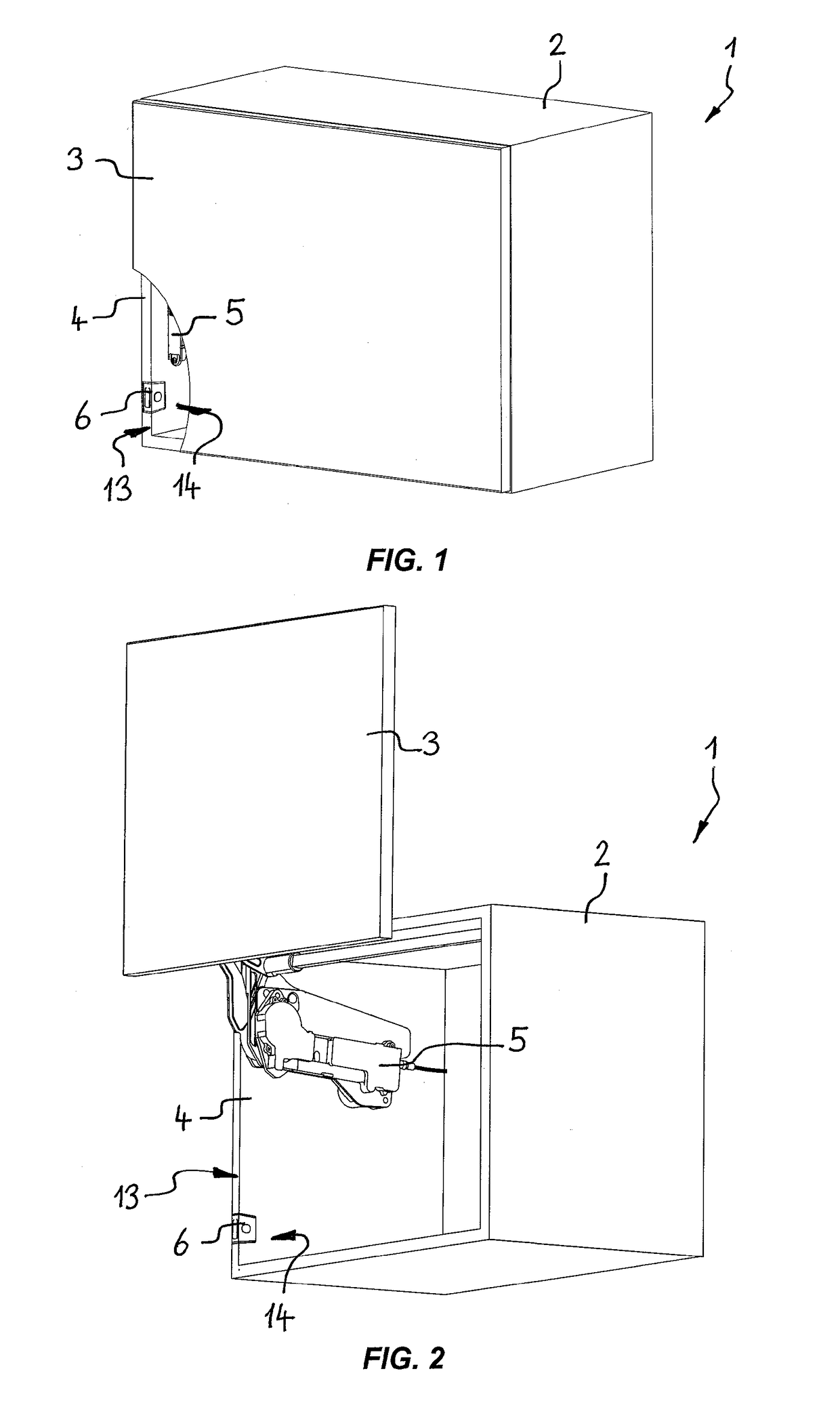
[0031]FIGS. 1 and 2 show a container according to the invention, wherein the container is formed as a cabinet 1 and comprises a first element in form of a shell 2 and a second element in form of a lid 3. The lid 3 is connected via a drive device 5 in form of a lid opener to the shell 2 and can be moved relative to the shell 2 from the closed position shown in FIG. 1 to the open position shown in FIG. 2. The drive device 5 includes, in this case, an electric drive (e.g. an electric motor), which enables an automatic displacement of the lid 3.

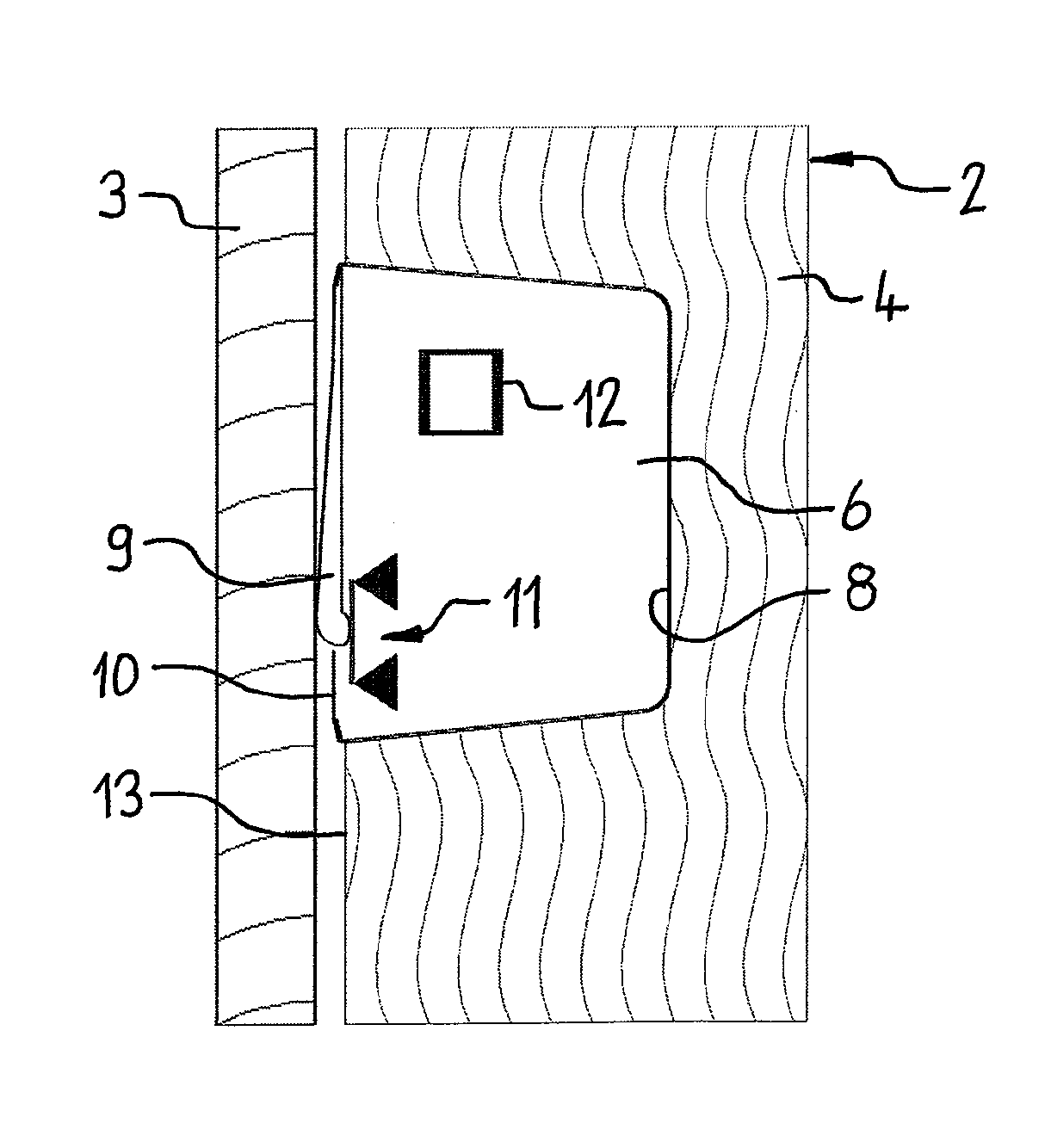
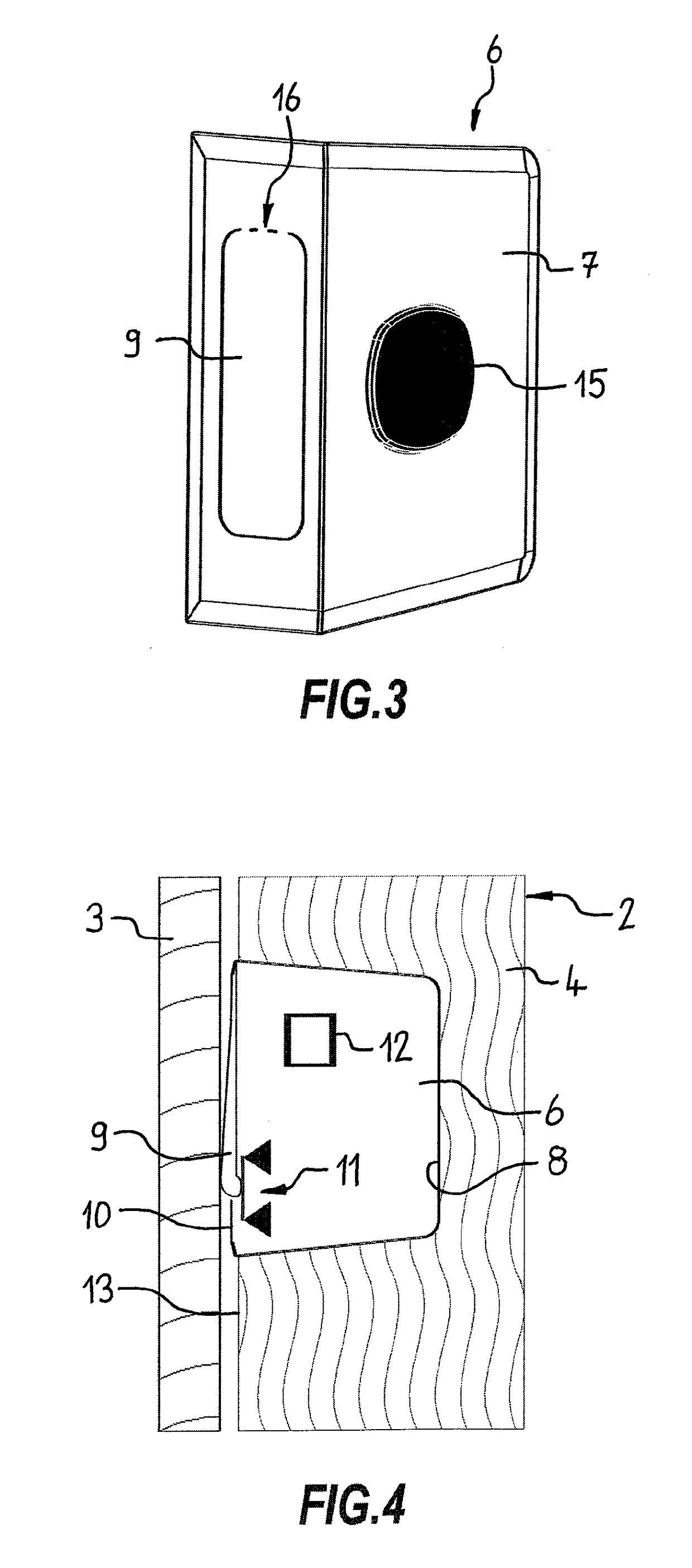
[0032]The shell 2 has a side wall 4, into which a deformation measuring unit 6 is incorporated. The deformation measuring unit 6 is shown in detail in FIGS. 3 and 4. FIG. 4 shows a partial cross-sectional view through the cabinet 1 of FIG. 1 with the lid 3 in its closed position. Furthermore, the deformation measuring unit 6 is shown schematically in a longitudinal sectional view.

[0033]The deformation measuring unit 6 includes an accommodation el...

second embodiment

[0036]In FIGS. 5 to 8, a container according to the invention is shown in the form of a cabinet 30, having a first element in form of a shell 31 and a second element in the form of a pullout / drawer 32. In FIG. 5 the shell 31 is shown schematically by indication of the outer edges. The pullout 32 includes a front 33 (FIG. 8) and a support element 34. The support element 34 is arranged linearly displaceable within the shell 31 and is driven electrically by a drive device 35, so that by actuating the drive device 35 the pullout 32 can be driven out and again back into the shell 31. A solution may also be considered, in which the pullout is only expelled a bit from the shell 31 and the further movement is achieved by free-wheeling or manually. Several shelves 36 are arranged on the support element 34 for storing objects. Between the front 33 and the support element 34, a deformation measuring unit 37 is provided, which actuates the drive device 35.

[0037]The deformation measuring unit 37...


PUM


Abstract

Container comprisinga first element 2 and at least a second element 3 movable relative to the first element 2 between a closed position and an open position, and a drive device 5 for moving the second element 3, wherein at least one deformation measuring unit 6 is provided with a deformation sensor 11 on at least one of the elements 2, 3 for detecting a force exerted on one of the elements 2, 3 andwherein a control unit 12 is provided for receiving and evaluating a deformation signal transmitted by the deformation measuring unit 6 and is provided for actuating the drive device 5.

Description

CROSS-REFERENCE TO RELATED APPLICATIONS[0001]This application is the U.S. national stage of PCT / EP2014 / 059535 filed May 9, 2014, which claims priority of German Patent Application 10 2013 104 866.8 filed May 11, 2013.FIELD OF THE INVENTION[0002]The invention relates to a container having a first element and at least a second element movable relative to the first element between a closed position and an open position, as well as a drive device for moving the second element. The container can be a piece of furniture, a household appliance, as for example a kitchen appliance or built-in kitchen appliance, or a vending machine.BACKGROUND OF THE INVENTION[0003]A piece of furniture of the above named type is known from WO 2008 / 141348 A2. The piece of furniture has a first element in form of a furniture shell and a second element in form of a movable flap. By means of the drive device, the flap can be automatically transferred into an open or a closed position. For actuating, i.e. switchin...

Claims


Application Information

Patent Timeline
Patent Type & Authority Patents(United States)
IPC IPC(8): E05F15/73B65D43/26H03K17/96H03K17/965E05F15/611A47B88/457E05D15/46
CPCE05F15/73B65D43/26E05F15/611H03K17/964H03K17/965A47B88/457E05D15/46E05Y2400/852E05Y2400/86E05Y2900/20H03K2217/9651
Inventor BARKAU, RENE
Owner KESSEBOHMER HLDG KG
Why Eureka
Try Eureka