System and method for monitoring and balancing voltage of individual battery cells within a battery pack

a battery pack and individual battery technology, applied in secondary cells, battery service/maintenance, instruments, etc., can solve the problems of limiting the volume and geometry of the battery pack, cost prohibitive to redesign and repackage the battery components for all applications, and it is unlikely that a single or a few special purpose designs would be suitable for a wide range of applications. , to achieve the effect of reducing system design costs, reducing design cost and time, and easily varying the geometric design of the battery

Active Publication Date: 2017-10-17
A123 SYSTEMS LLC
View PDF16 Cites 4 Cited by
  • Summary
  • Abstract
  • Description
  • Claims
  • Application Information

AI Technical Summary

Benefits of technology

[0004]A battery cell monitor and voltage balance board that is scalable may allow a battery pack manufacturer to reduce design cost and time. Further, a scalable design for battery cell monitor and voltage balance boards may allow a battery pack to be comprised of one or more battery cell stacks that vary in a number of battery cells. Thus, a scalable battery cell monitor and voltage balance board may provide a way to easily vary the geometric design of a battery pack to accommodate varying customer packaging requirements.
[0005]The present description may provide several advantages. For example, the approach may lower system design costs by permitting a single battery monitor and voltage balance board design to be used to construct a plurality of battery pack configurations. In addition, the present approach may reduce system cost since battery control electronics and control software may not have to be redesigned for every application. Further, the approach may allow for the construction of a wide variety of battery pack geometries. Further still, the approach draws substantially equal amounts of current from battery cells powering control circuitry. Further still, the approach has redundant checks to ensure proper system configuration.

Problems solved by technology

Further, as battery packs are integrated into an increasing variety of vehicle types, vehicle packaging constraints may limit battery pack volume and geometry.
The inventors herein have recognized that it may be cost prohibitive to redesign and repackage battery components for all applications.
Further, it is unlikely that a single or a few special purpose designs would be suitable for a wide range of applications.
Further still, the approach has redundant checks to ensure proper system configuration.

Method used


Image

  • System and method for monitoring and balancing voltage of individual battery cells within a battery pack
  • System and method for monitoring and balancing voltage of individual battery cells within a battery pack
  • System and method for monitoring and balancing voltage of individual battery cells within a battery pack

Examples


Embodiment Construction

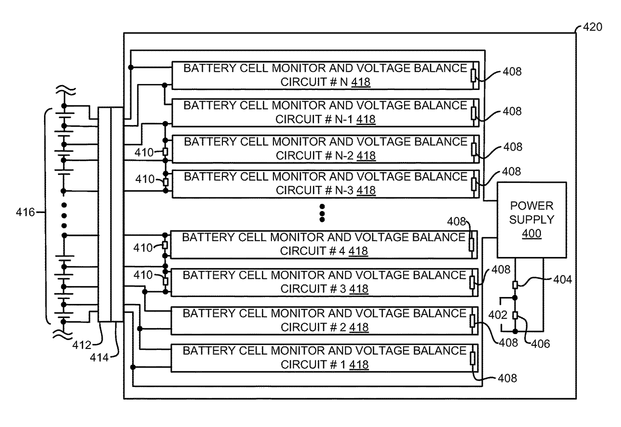
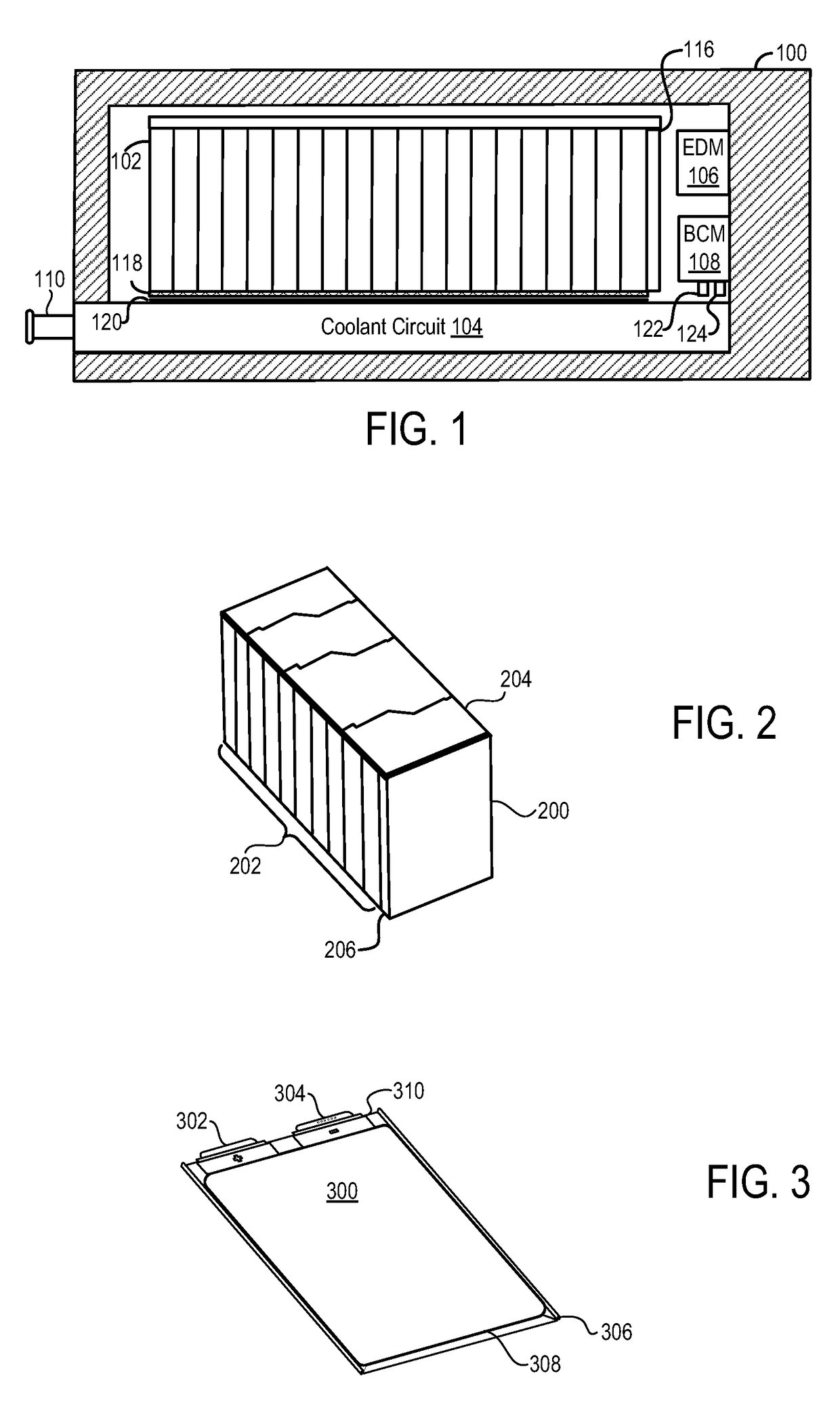
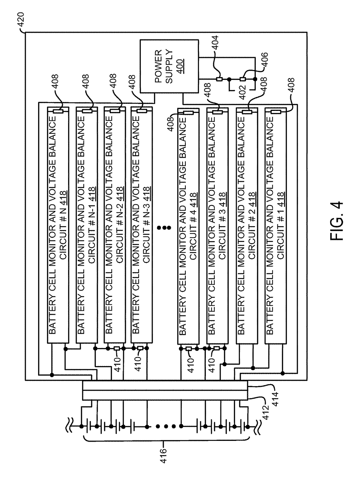
[0018]The present description is related to controlling voltage of individual battery cells within a battery pack supplying power to a vehicle. In one embodiment, the battery pack may be designed to include an enclosure and structure as is illustrated in FIG. 1. The battery pack may be comprised of one or more battery cell stacks, one of which is illustrated in FIG. 2. The battery cell stacks are comprised of a plurality of battery cells, one of which is illustrated in FIG. 3. Battery cell voltage monitoring and balancing is provided by scalable circuitry as is illustrated in FIG. 4-7.

[0019]Referring now to FIG. 1, an example battery pack 100 is illustrated. Battery pack 100 includes battery cell stack 102, coolant circuit 104, electrical distribution module (EDM) 106, and BCM 108. In the depicted embodiment, coolant enters the coolant circuit at coolant connector 110. Further, coolant circuit 104 is in thermal communication with battery cell stack 102 via conductive grease 118 and ...


PUM

PropertyMeasurementUnit
output voltageaaaaaaaaaa

Abstract

Systems and methods for a scalable battery controller are disclosed. In one example, a circuit board coupled to a battery cell stack is designed to be configurable to monitor and balance battery cells of battery cell stacks that may vary depending on battery pack requirements. Further, the battery pack control module may configure software instructions in response to a voltage at a battery cell stack.

Description

CROSS REFERENCE TO RELATED APPLICATIONS[0001]This application claims priority from International Patent Application Serial No. PCT / US2011 / 020692, filed Jan. 10, 2011 and entitled SYSTEM AND METHOD FOR MONITORING AND BALANCING VOLTAGE OF INDIVIDUAL BATTERY CELLS WITHIN A BATTERY PACK, which claims priority to U.S. Provisional Patent Application Ser. No. 61 / 293,861, filed Jan. 11, 2010 and entitled SYSTEM AND METHOD FOR MONITORING AND BALANCING VOLTAGE OF INDIVIDUAL BATTERY CELLS WITHIN A BATTERY PACK, the entirety of both of which are hereby incorporated herein by reference for all intents and purposes.TECHNICAL FIELD[0002]The present description relates to a scalable system for constructing and operating a battery pack supplying power to a vehicle.BACKGROUND AND SUMMARY[0003]In an effort to reduce vehicle emissions and reduce reliance on limited oil reserves, manufactures are increasingly moving toward battery packs as a mobile power source. In some vehicle configurations the batter...

Claims


Application Information

Patent Timeline
Patent Type & Authority Patents(United States)
IPC IPC(8): G01N27/416H02J7/00H01M10/42H01M10/44H01M10/48G01R31/36H01M2/10H01M10/613H01M16/00H01M50/209H01M50/284
CPCH02J7/0016H01M10/4257H01M10/441H01M10/482G01R31/3658H01M2/1077H01M10/613H01M16/00H01M2010/4271H01M2220/20Y02T10/7055B60L2240/547B60L58/18B60L58/22G01R31/396Y02T10/70Y02E60/10H01M50/284H01M50/209
Inventor FIREHAMMER, PAUL W.MOORHEAD, BRIAN C.
Owner A123 SYSTEMS LLC
Why Eureka
Try Eureka