
High-speed, dual-sided shoe sorter with offset induct

a sorter and offset inductance technology, applied in sorting, conveyor parts, transportation and packaging, etc., can solve the problems of affecting the speed of the sorter, and affecting the impact of the articl

Active Publication Date: 2017-10-24
INTELLIGRATED HEADQUATERS LLC
View PDF11 Cites 10 Cited by
  • Summary
  • Abstract
  • Description
  • Claims
  • Application Information

AI Technical Summary

Benefits of technology

The patent describes a high-speed conveyor system that uses pushers or shoes to sort items on a conveyor belt. A guide is used to control the pushers so that they engage the items at a slow speed and then accelerate them to a higher speed. This allows for faster throughput and reduces the risk of the pushers causing damage to the items. Overall, the system is designed to be efficient and effective at sorting items quickly and safely.

Problems solved by technology

This speed limitation was also imposed on the divert switches and guides that also were straight angled.
High speeds during the divert tended to impact and tumble the articles.

Method used


Image

  • High-speed, dual-sided shoe sorter with offset induct
  • High-speed, dual-sided shoe sorter with offset induct
  • High-speed, dual-sided shoe sorter with offset induct

Examples


first embodiment

[0046]This first embodiment is for a three (3) path sortation conveyor 500 having three paths for pushers 512a, 512b to follow. Two paths are outboard, path 522g and path 523e, and one is in the middle or center path 523e. For this embodiment, all articles 516 are received on first path 503a. To show the downstream movement of article 516 and pusher 512a, a series of snapshots (516a-516f) are shown as article 516 moves from the first lane 503 and, in a two-step process, onto second divert 514b. Article 516 is shown entering onto the moving sortation conveyor 500 at position 522a. In the first step, induct pusher 512a is carried on moving conveying surface 510 and contacts and follows an arcuate rail underneath moving slats (not shown). The contact with the arcuate rail moves article 516 laterally along arcuate path 522b to article location 516b. Article 516 is then moved laterally by pusher 512a along central arcuate path 522c to article location 516c which is in second lane 503b. F...

second embodiment

[0048]FIG. 6 shows an example of three direction switch 524a used in FIG. 5 to divert articles 516 onto any of paths 523c, 522e, or 523d. FIG. 7 shows an alternate embodiment of dual lane sortation conveyor 700 having a conveying surface 702 on an endless belt or apron 706. Dual lane sortation conveyor 700 of the second embodiment has two central parallel paths 723d and 323d extending downstream for pushers 702, and two outer paths 722g and 723e parallel and adjacent to respective first side 701a and second side 701b.

[0049]Article 516 is shown entering onto the moving sortation conveyor 700 at position 722a. In the first step, induct pusher 710a is carried on moving conveying surface 703 and contacts and follows an arcuate rail underneath moving slats 708 (not shown). The contact with the arcuate rail moves article 516 laterally along arcuate path 722b to article location 516b. Arcuate path 722b crosses over path 323d with a crossover. Article 516 is then moved laterally by pusher ...


PUM


Abstract

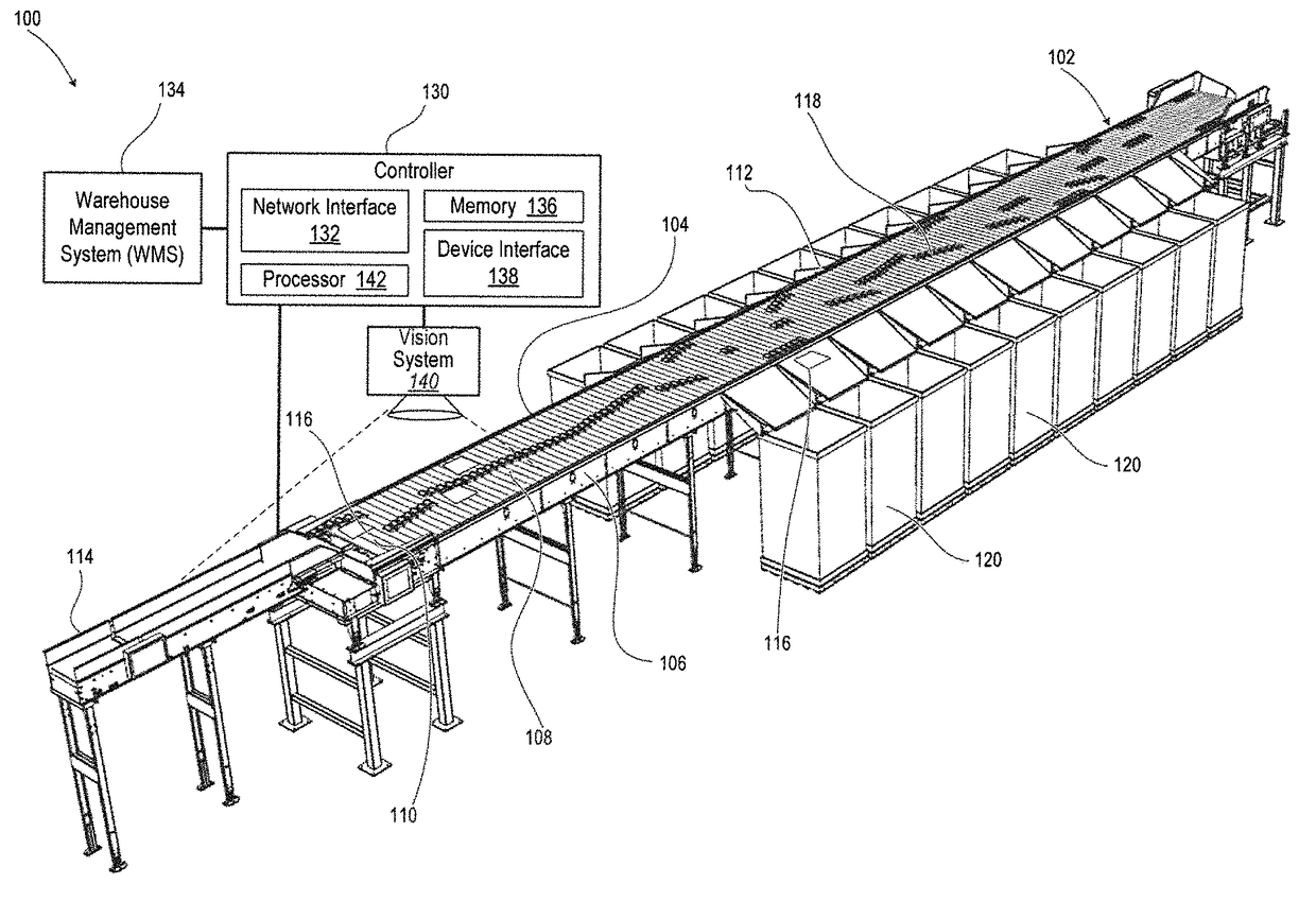
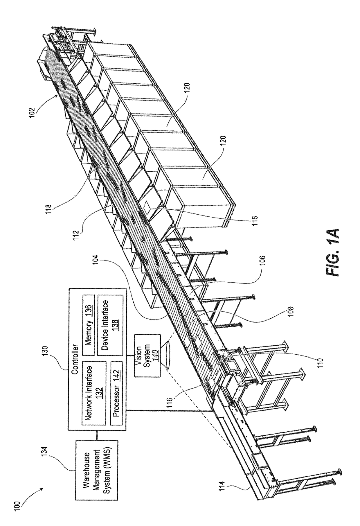
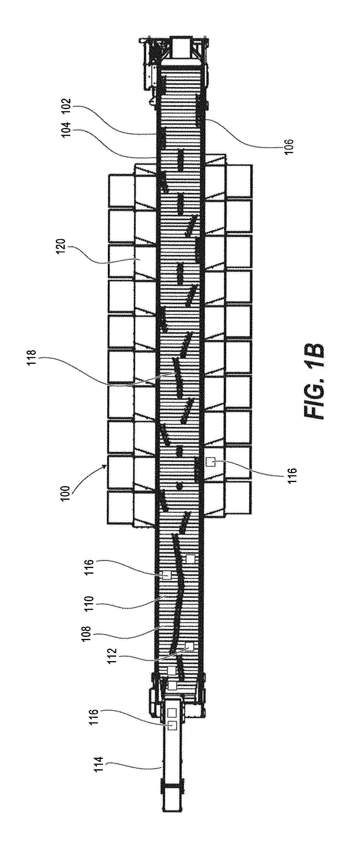
A sortation conveyor has an endless apron supported for longitudinal movement on an elongate frame. An induction conveyor deposits articles on an offset lateral portion of a top conveying run of the apron. A pin guide assembly is coupled between the elongate frames and is upwardly presented to selectively receive the pin of pushers that laterally move across the apron. An upstream pre-sort section thereof positions articles from the offset lateral portion to an opposite lateral portion of the top conveying run. A downstream divert section of the pin guide assembly selectively diverts the articles to a divert target on the corresponding lateral side to the selected one of offset lateral position and the opposite lateral position.

Description

CLAIM OF PRIORITY UNDER 35 U.S.C. §119[0001]The present Application for patent claims priority to (i) U.S. Provisional Patent Application No. 62 / 157,501 filed on 6 May 2015 and entitled “Dual Sided Shoe Sorter with Offset Induction Lane”; and (ii) Provisional Patent Application No. 62 / 308,401 filed on 15 Mar. 2016 and entitled “High-Speed Linear Sortation Conveyor with Selective Top Reinduction”; both assigned to the assignee hereof, and both hereby expressly incorporated by reference in their entirety.BACKGROUND[0002]1. Technical Field[0003]The present disclosure relates generally to linear sortation conveyors, also known as shoe sorters, and their components, and is particularly directed to dual sided shoe sorters.[0004]2. Description of the Related Art[0005]Sortation conveyors are essential components of high volume distribution and fulfillment operations. A sortation conveyor system typically conveys and distributes articles along moving conveyor surfaces, and diverts selected a...

Claims


Application Information

Patent Timeline
Patent Type & Authority Patents(United States)
IPC IPC(8): B65G47/10B65G47/46B07C5/36B07C3/06B65G47/76
CPCB07C3/06B65G47/766B65G47/46B07C5/36B65G47/844
Inventor ZIMMER, JUSTIN J.WIENEKE, JACOB D.TURCO, ANTHONY J.SAURBER, III, WILLIAM M.HUNTER, AARON K.RUGH, JOHN WILLIAMSKOENINGER, TIMOTHY A.OTTO, MATTHEW RYANSEBASTIAN, JARL NICHOLAS
Owner INTELLIGRATED HEADQUATERS LLC
Learn More