Microstrip antenna

a microstrip antenna and antenna technology, applied in the direction of antennas, slot antennas, basic electric elements, etc., can solve the problems of inability to say that the antenna has sufficient performance for use as a gnss antenna, the size of the microstrip antenna increases inevitably, and it is difficult to obtain the required axial ratio, etc., to achieve excellent axial ratio

Active Publication Date: 2017-10-24
YOKOWO CO LTD
View PDF9 Cites 1 Cited by
  • Summary
  • Abstract
  • Description
  • Claims
  • Application Information

AI Technical Summary

Benefits of technology

[0016]The invention has been accomplished in consideration of recognition of such circumstances. It is an object of the invention to provide a microstrip antenna capable of obtaining an excellent axial ratio in a required frequency band while being more compact than in the background art.

Problems solved by technology

However, even in the frequency characteristics of FIG. 13, the axial ratio deteriorates up to 4.5 dB within the GNSS frequency band so it cannot be said that the antenna has sufficient performance for use as a GNSS antenna.
In this manner, the one-point-feed microstrip antenna has a simple configuration but the size of the microstrip antenna increases inevitably when the operable frequency band is intended to be widened.
It is difficult to obtain the required axial ratio (for example, which is equal to or lower than 4 dB) within the GNSS frequency band even if the size of the microstrip antenna is increased.
Thus, the size of the substrate as a microstrip antenna becomes large.

Method used


Image

  • Microstrip antenna
  • Microstrip antenna
  • Microstrip antenna

Examples


Embodiment Construction

[0043]Preferred embodiments of the invention will be described below in detail with reference to the drawings. In the embodiments, the same or equivalent constituent elements, members, etc. shown in the drawings will be referred to by the same reference numerals correspondingly and respectively, and duplicate description thereof will be omitted suitably. In addition, each embodiment does not restrict the invention but is simply exemplary, and all features described in the embodiment or their combinations are not always essential to the invention.

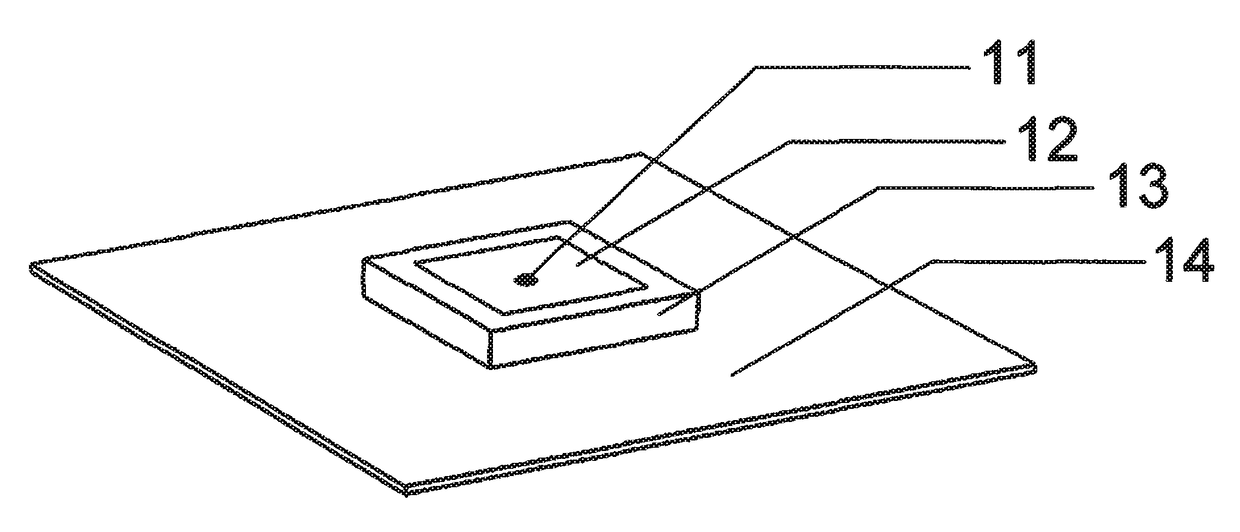
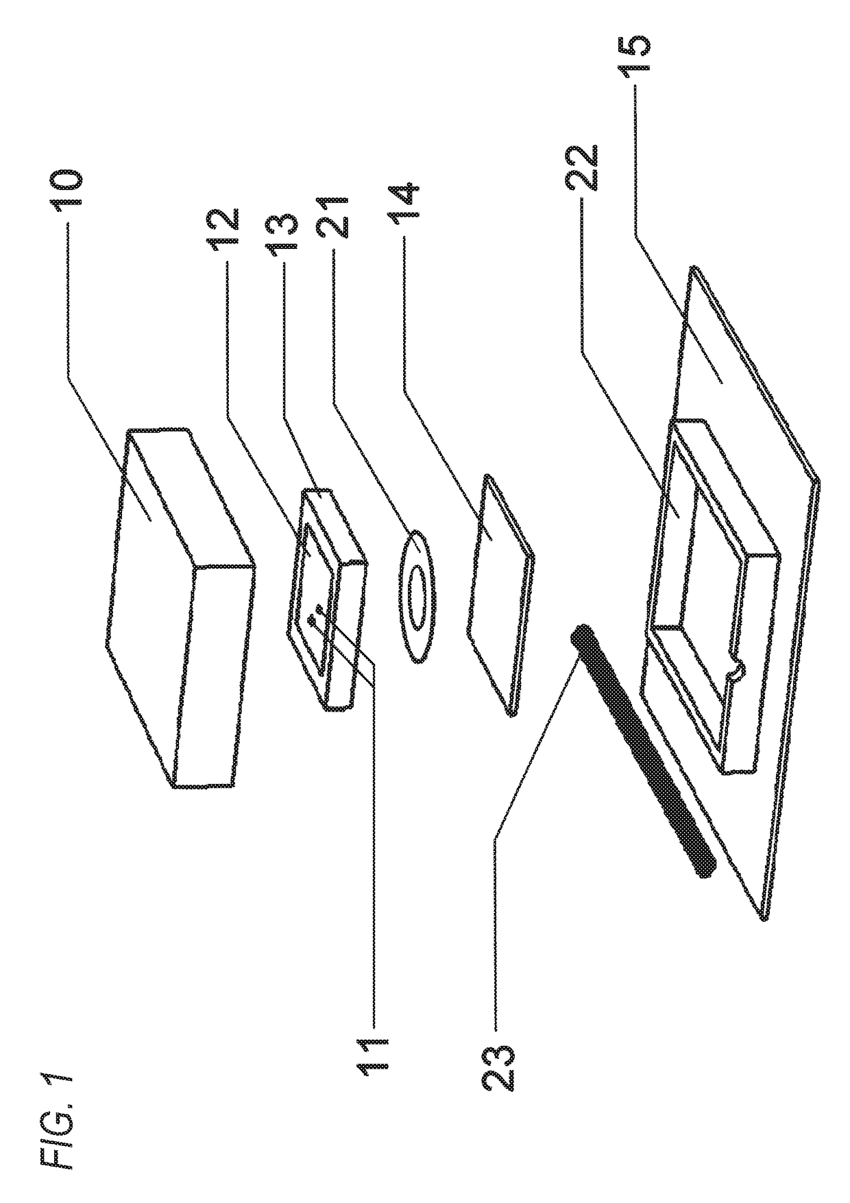
[0044]FIG. 1 is an exploded perspective view of a microstrip antenna according to an embodiment of the invention. In FIG. 1, a ceramic plate 13 (dielectric plate) is provided (for example, bonded by a double sided tape 21) on a central portion of a substrate 14. A silver electrode 12 (patch electrode) serving as an antenna element is formed on a main surface of the ceramic plate 13. Electric power is fed to the silver electrode 12 by two fee...


PUM


Abstract

A microstrip antenna has two feed points. The microstrip antenna includes a feeder circuit which is configured to feed, to the two feed points, electric signals whose phases are different by 90° from each other. The feeder circuit includes a Wilkinson coupler unit and a phase-shift unit each of which is formed as a lumped constant circuit.

Description

TECHNICAL FIELD[0001]The present invention relates to a microstrip antenna having two feed points.BACKGROUND ART[0002]GNSS (Global Navigation Satellite Systems) is a general term for positioning systems using satellite. The GNSS includes GPS (Global Positioning System), GLONASS (Global Navigation Satellite System) and GALILEO. Frequency bands of the respective satellite positioning systems are as follows.[0003]GPS (L1) 1575.42±1.023 MHz[0004]GALILEO (E1) 1575.42±2.046 MHz[0005]GLONASS (L1) 1595.051 MHz to 1605.8865 MHz[0006]Therefore, in case that full bandwidth of the GPS, the GLONASS and the GALILEO is intended to be covered by one microstrip antenna, requirements of the antenna such as an axial ratio have to be satisfied in a wide frequency band (whose bandwidth is 32.5125 MHz) of 1573.374 MHz to 1605.8865 MHz. The frequency band of 1573.374 MHz to 1605.8865 MHz will be hereinafter also mentioned as “GNSS frequency band”.[0007]FIG. 9 is a perspective view of a first configuration...

Claims


Application Information

Patent Timeline
Patent Type & Authority Patents(United States)
IPC IPC(8): H01Q9/04H01Q13/10H03H7/48
CPCH01Q9/0442H01Q13/106H01Q9/0435H03H7/48
Inventor SAMPO, TAKESHIKOWAITA, KAZUHIRO
Owner YOKOWO CO LTD
Why Eureka
Try Eureka