Bale processor and flail for use with same

a technology of bale processor and flail, which is applied in the field of bale processor, can solve the problems that the prior art bale processor has limited ability to output chopped material at different lengths, and achieve the effect of increasing the throw distance of the material chopped by the flail and increasing the throw distance of the filamentary material

Active Publication Date: 2017-10-31
VERMEER MFG CO
View PDF34 Cites 3 Cited by
  • Summary
  • Abstract
  • Description
  • Claims
  • Application Information

AI Technical Summary

Benefits of technology

[0008]According to a further embodiment, a bale processor includes a hopper for receiving baled material, a discharge opening for outputting chopped material, and a processing section having primary and secondary rotors. The primary rotor has an axis of rotation and a rotatable flail to chop the material from the bale received in the hopper. The secondary rotor is rotatable to chop the material after being chopped by the primary rotor, and the secondary rotor is offset from the primary rotor such that the primary rotor is between the secondary rotor and the discharge opening. The flail includes a pivot tube for rotating about the axis of rotation, first and second hammers secured to the pivot tube, and a paddle. The paddle is positioned between and secured to the first and second hammers to generate airflow when the first and second hammers are rotated at an operating speed, thereby increasing a throw distance of the material chopped by the flail.
[0009]According to a still further embodiment, a flail is provided for use in a bale processor to yield a chopped filamentary material. The flail includes a pivot tube for rotating about an axis, first and second hammers secured to the pivot tube, and a paddle. The paddle is positioned between and secured to the first and second hammers to generate airflow when the first and second hammers are rotated at an operating speed, thereby increasing a throw distance of the chopped filamentary material.

Problems solved by technology

In general, prior art bale processors have limited abilities to output chopped material at different selected lengths.

Method used


Image

  • Bale processor and flail for use with same
  • Bale processor and flail for use with same
  • Bale processor and flail for use with same

Examples


Embodiment Construction

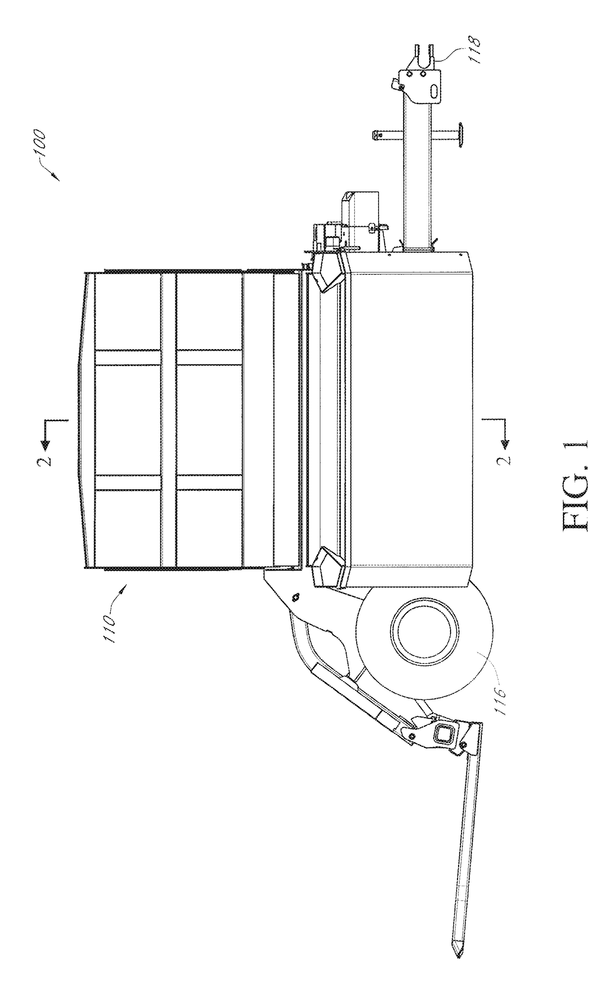
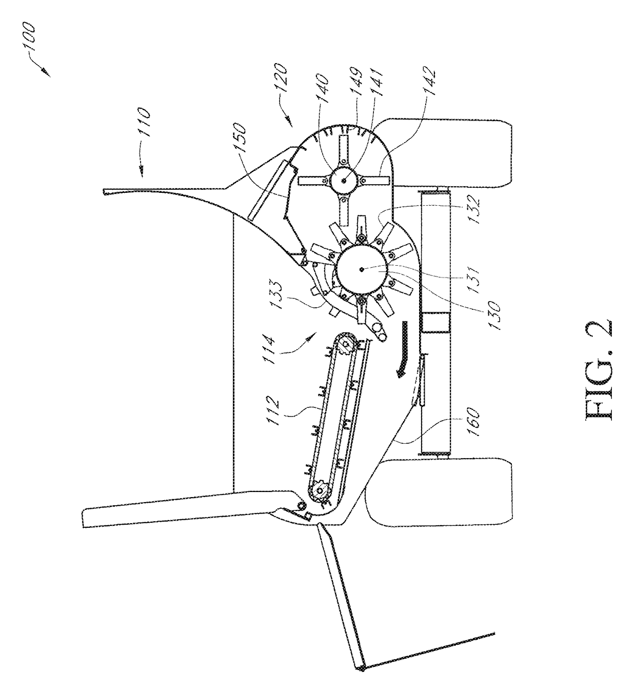
[0032]FIGS. 1 through 3 illustrate a bale processor 100, according to one embodiment. The bale processor 100 includes a hopper (or “tub”) 110 for receiving bale of forage, bedding, or another bale filamentary material (e.g., hay, straw, corn stover, etc.); a processing section 120 that includes primary and secondary rotors 130, 140; and a discharge opening 160 for outputting processed (or “chopped”) bale filamentary material. The terms “primary” and “secondary” are used herein for convenience in referring to the rotors 130, 140 and indicate that the bale filamentary material interacts with the rotor 130 before interacting with the rotor 140 (as described in detail below).

[0033]The hopper 110 of embodiment 100 is consistent with “hopper 12” of WO2013 / 066287. However, as will be appreciated by those skilled in the art, the hopper 110 may be of various configurations, shapes, and sizes. A conveyor 112, as shown in FIGS. 2 and 3, may be included in the hopper 110 to rotate a bale inside...


PUM


Abstract

In one embodiment, a bale processor includes a hopper for receiving baled material, a discharge opening for outputting chopped material, and primary and secondary rotors. The primary rotor has an axis of rotation and a rotatable flail to chop the material from the bale received in the hopper. The secondary rotor is rotatable to chop the material after being chopped by the primary rotor, and the secondary rotor is offset from the primary rotor such that the primary rotor is between the secondary rotor and the discharge opening. The flail includes a pivot tube for rotating about the axis, first and second hammers secured to the pivot tube, and a paddle. The paddle is positioned between and secured to the first and second hammers to generate airflow when the first and second hammers are rotated at an operating speed, thereby increasing a throw distance of the chopped material.

Description

RELATED APPLICATIONS[0001]This application claims priority to U.S. Patent Application Ser. No. 62 / 077,142, filed Nov. 7, 2014. This application is also a Continuation-In-Part of PCT Patent Application Serial No. PCT / US14 / 54113, filed Sep. 4, 2014, whichs claim priority to U.S. patent application Ser. No. 14 / 290,558, filed May 29, 2014. This application is also a Continuation-in-Part of PCT Patent Application Serial No. PCT / US2014 / 063336, filed Oct. 31, 2014, which claims priority to U.S. Provisional Application Ser. No. 61 / 898,037, filed Oct. 31, 2013. Priority is claimed to each, and the disclosure of each is incorporated herein in its entirety by reference.BACKGROUND[0002]The current invention relates generally to bale processors. Bale processors are devices used to spread the content of bales of bale filamentary material in a controlled way for reasons such as mulching or feeding livestock. Examples of bale processors are shown in PCT / US2013 / 023153 filed by Vermeer Manufacturing ...

Claims


Application Information

Patent Timeline
Patent Type & Authority Patents(United States)
IPC IPC(8): B02C13/00B02C13/28A01F29/00A01K5/00
CPCB02C13/28A01K5/005A01K5/002A01F29/005
Inventor STAM, PHILGRAHAM, LUCASMUCHTAR, WANTILANDON, DAVIDJOHNSON, BJORNEGGING, PHILSCHIFERL, TYLERMUSHITZ, LUKE
Owner VERMEER MFG CO
Why Eureka
Try Eureka