Supercharge Your Innovation With Domain-Expert AI Agents!

Proximity sensor monitor

a technology of proximity sensor and monitor, which is applied in the direction of electronic switching, pulse technique, instruments, etc., can solve the problems of equipment failing to do something, not always possible,

Active Publication Date: 2017-10-31
ULTRA PCS LTD
View PDF6 Cites 4 Cited by
  • Summary
  • Abstract
  • Description
  • Claims
  • Application Information

AI Technical Summary

Benefits of technology

[0034]By providing a separate proximity sensor comprising a proximity sensor monitor having a separate measurement path to common electrical and impedance components enables separate measurement and monitoring of the proximity of a target, thereby satisfying the Functional Hazard Analysis requirements. Since the measurement path of the proximity sensor monitor is independent of the proximity sensor, however, the excitation frequency used to generate the proximity monitor signal and the excitation frequency used to generate an electrical signal applied to the series connected electrical and impedance components by a signal generator of the proximity sensor will be different. As such, the processor of the proximity sensor monitor is advantageously configured to compensate for this difference, which would otherwise cause the independent measurements to differ by too large a degree to give the user any confidence in the measurements.

Problems solved by technology

In essence, failure conditions may result in a piece of equipment failing to do something, or inadvertently doing something it shouldn't.
However, this is not always possible due to weight and space constraints in locating the secondary detector.

Method used


Image

  • Proximity sensor monitor
  • Proximity sensor monitor
  • Proximity sensor monitor

Examples


second embodiment

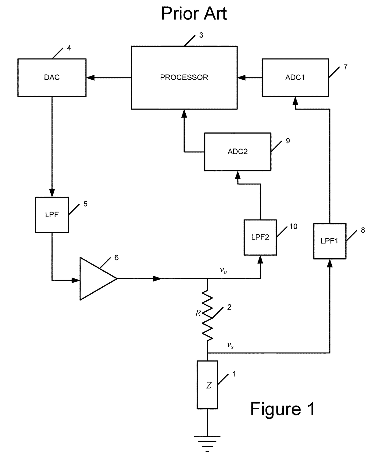
[0153]In the frequency offset compensation, the processor switches the switch to measure VO and performs a Discrete Fourier Transform (DFT) on the first measured VO. This DFT reveals the phase of the first VO measured at a first time. The switch then switches to measure VS and performs a DFT to reveal the phase of the VS measured at the second time. If there is a frequency offset between proximity sensor and proximity sensor monitor, the phase will have rotated between VO and VS. The processor then uses the phases of the measured VO and a previously measured VO (VO-1 for example) to perform an extrapolation to calculate a phase of a VO measurement if a VO measurement was taken at the second time (i.e. the same time as the VS measurement). This calculated phase can then be used to apply a phase offset to either of the VO measurements such that the calculations of impedance may be performed as described above with reference to FIG. 2.

[0154]In a first version of the extrapolation metho...

third embodiment

[0157]In the frequency offset compensation, the proximity sensor monitor comprises a counter unit to receive and count the clock signal or excitation frequency signal from the proximity sensor. From this, the frequency can be monitored and compared to the frequency of the proximity sensor monitor clock or excitation frequency, and a phase offset per measurement block that can be determined. The processor uses the determined phase offset and applies this phase correction value to a measured VO such that is substantially aligns with the phase of the a VO signal if it were measured at the same time as the measured VS. The calculations of impedance may now be performed as described above with reference to FIG. 2.

[0158]An advantage of using a counting unit is that no calculation of the phase offset is required (either by interpolation or extrapolation). However, a counting unit requires multiple samples of the clock to determine the frequency of the clock being monitored accurately. Many...

first embodiment

where {circumflex over (V)}S and {circumflex over (V)}R are the complex voltage amplitude estimates measured by the system at the device 20 and at the output of the difference amplifier 72 respectively. Cross- and auto-power spectral estimators are then formed as in the

[0162]This version benefits from the avoidance of the need to calculate the difference voltage parameter ÂR from ÂS and Âo. However a difference amplifier is required which is highly accurate and stable.

[0163]A third version of the proximity sensor system will now be described with reference to FIG. 5. This version is similar to the first embodiment of the present invention illustrated in FIG. 3 and hence like reference numerals are used for like components. This version differs from that shown in FIG. 3 in that multiple measurement channels are provided for simultaneous measurement of the voltages sequentially. In this version there are two channels operating so that at any point in time a measurement of both voltage...


PUM


Abstract

The present invention generally relates to proximity sensor monitors and proximity monitor systems incorporating proximity sensor monitors. A proximity sensor monitor measures the impedance or other electrical characteristics of a proximity sensor component to determine the presence of a target. The proximity sensor monitor performs this measurement independently of a separate proximity sensor. The proximity sensor monitor is configured to compensate for differences between the measurement frequency of the proximity sensor monitor and the driving frequency of the proximity sensor.

Description

FIELD OF THE INVENTION[0001]The present invention generally relates to proximity sensor monitors to and proximity monitor systems incorporating proximity sensor monitors.BACKGROUND OF THE INVENTION[0002]Recent changes in safety requirements in the aerospace industry have meant that more and more systems, subsystems and pieces of equipment form part of the Functional Hazard Analysis (FHA). The FHA identifies system failures and identifies the effects of these failures. Failures are tabulated and classified according the effects which that failure may cause and the safety objectives assigned according to the criteria are shown below:[0003]Failure conditionDevelopmentSafety objectives quantities requiredclassificationassurance level(probability per flight hour)CatastrophicA<1 × 10⁻⁹Hazard / SevereB<1 × 10⁻⁷MajorC<1 × 10⁻⁵MinorD<1 × 10⁻³No safety effectENone[0004]In essence, failure conditions may result in a piece of equipment failing to do something, or inadvertently doing s...

Claims


Application Information

Patent Timeline
Patent Type & Authority Patents(United States)
IPC IPC(8): G01D5/24G01D3/08G01D5/20H03K17/95G01B7/00G01B7/14G01R31/28
CPCG01D5/24G01B7/003G01B7/14G01D5/20H03K17/9502G01D3/08G01R31/2829G01B7/023G01D5/2006
Inventor STOTHERS, IAN MCGREGORSCOTT, IVAN ANTHONYPEACHEY, JAMES
Owner ULTRA PCS LTD
Features
  • R&D
  • Intellectual Property
  • Life Sciences
  • Materials
  • Tech Scout
  • Unparalleled Data Quality
  • Higher Quality Content
  • 60% Fewer Hallucinations
Learn More