Gas-filling apparatus and method for filling gas

a gas-filled apparatus and gas-filled technology, applied in the direction of container discharging methods, container filling under pressure, transportation and packaging, etc., can solve the problem of downsizing of the compressor

Active Publication Date: 2017-11-07
KOBE STEEL LTD
View PDF60 Cites 6 Cited by
  • Summary
  • Abstract
  • Description
  • Claims
  • Application Information

AI Technical Summary

Benefits of technology

[0008]In the present invention, the first compression filling operation is conducted and is thereafter shifted to the second compression filling operation. That is, in the event of supplying the gas to the pressure accumulator, the supply of the gas from the gas supply source and the supply of the gas from the storage portion are not conducted at the same time. Therefore, a complicated control for filling of the gas into the pressure accumulator by the gas-filling apparatus can be avoided. In addition, the first compression filling operation is conducted until the pressure of the gas at the outflow end or the pressure corresponding to the pressure of the gas at the outflow end reaches the predetermined pressure. Thereafter, the first compression filling operation is shifted to the second compression filling operation; therefore, a range of pressure increase of the gas in the compressor can be reduced. As a result, the compressor may be downsized. That is, the number of compression stages of a compression chamber of the compressor can be reduced; therefore, a smaller compressor can be adopted.
[0028]As described above, according to the present invention, a complicated control for filling of the gas into the pressure accumulator by the gas-filling apparatus can be avoided.

Problems solved by technology

As a result, the compressor may be downsized.

Method used


Image

  • Gas-filling apparatus and method for filling gas
  • Gas-filling apparatus and method for filling gas
  • Gas-filling apparatus and method for filling gas

Examples


first embodiment

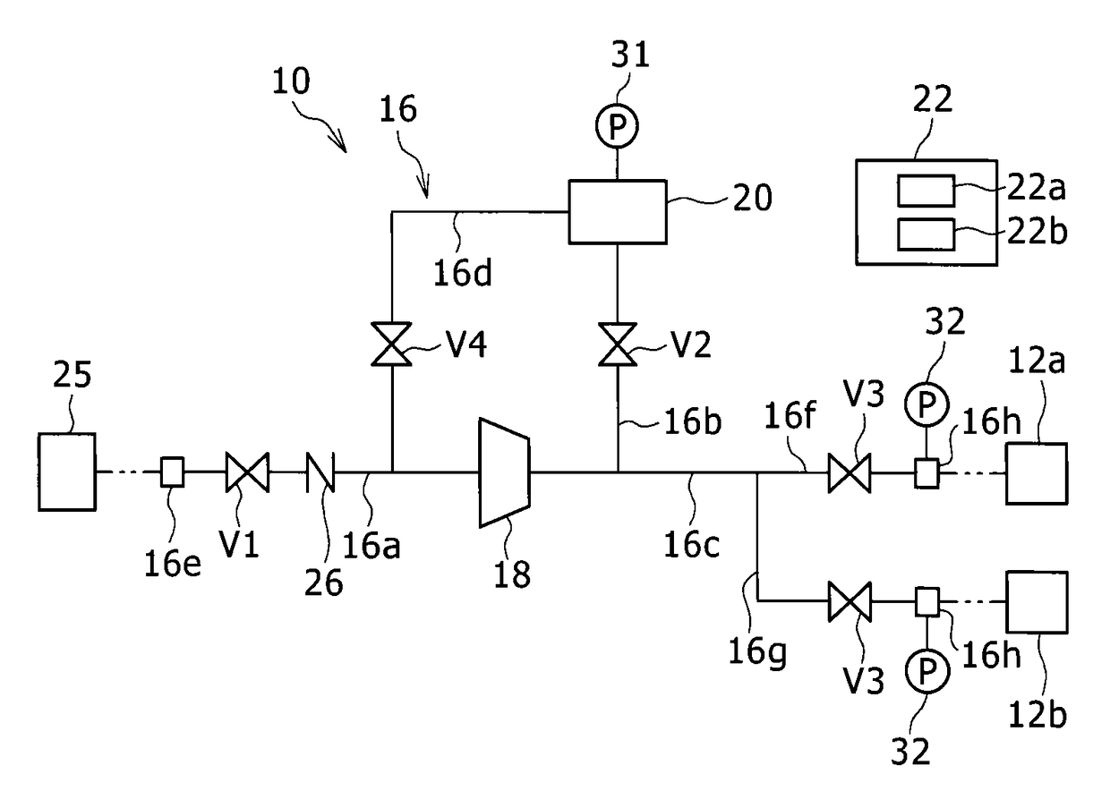
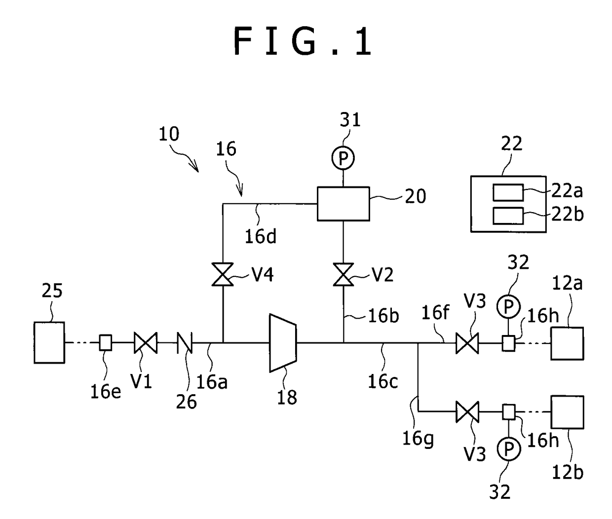
[0041]As illustrated in FIG. 1, a gas-filling apparatus 10 according to a first embodiment of the present invention serves to fill hydrogen gas (gas) into pressure accumulators 12a, 12b arranged at a hydrogen station, for example, serving as a hydrogen gas filling stand. The hydrogen gas having a preliminarily set predetermined pressure is stored in the pressure accumulators 12a, 12b. A dispenser not shown is connected to the pressure accumulators 12a, 12b and the hydrogen gas stored in the pressure accumulators 12a, 12b is supplied through the dispenser to a fuel-cell vehicle corresponding to a tank mounting unit.

[0042]The gas-filling apparatus 10 is provided with a gas flow passage 16 for distributing the hydrogen gas, a compressor 18 connected to the gas flow passage 16, a storage portion 20 connected to the gas flow passage 16, and a controller 22. The storage portion 20 is configured by a single container or plural containers.

[0043]The gas flow passage 16 includes a first flow ...

second embodiment

[0070]Next, a second embodiment of the present invention will be described. In addition, same reference numbers are assigned to components in the second embodiment, which are similar to those in the first embodiment, and those details will not be explained herein.

[0071]As illustrated in FIG. 3, the gas-filling apparatus 10 according to the second embodiment is provided with the gas flow passage 16. The gas flow passage 16 includes the first flow passage 16a, the second flow passage 16b, the third flow passage 16c, a sixth flow passage 16j, and a seventh flow passage 16k.

[0072]The inflow end 16e to which the gas supply source 25 is connectable is arranged at the upstream end of the first flow passage 16a. The downstream end of the first flow passage 16a is connected to the suction portion of the compressor 18. The check valve 26 and a flow regulating valve 27 are arranged in the first flow passage 16a. The flow regulating valve 27 is configured by an electric-operated valve, an open...

third embodiment

[0099]A third embodiment of the present invention is illustrated in FIG. 7. In the third embodiment, the storage portion 20 is configured to include a first tank portion 20a and a second tank portion 20b which stores gas with higher pressure than the first tank portion 20a. In the third embodiment, the hydrogen gas is filled in the pressure accumulators 12a, 12b only by the differential pressure filling operation from the second tank portion 20b. Same reference numbers are assigned to components in the third embodiment, which are similar to those in the first embodiment, and those details will not be explained herein.

[0100]The flow regulating valve 27 is arranged in the first flow passage 16a. The flow regulating valve 27 is configured by an electric-operated valve, an opening degree of which is regulatable.

[0101]The first tank portion 20a is connected to one end of the second flow passage 16b and is connected to one end of the fourth flow passage 16d. The second tank portion 20b is...


PUM


Abstract

A gas-filling apparatus includes a gas flow passage including an inflow end to which a gas supply source is connectable and an outflow end to which a pressure accumulator is connectable, a compressor, a storage portion, and an operation control portion conducting a first compression filling operation in which a gas supplied from the gas supply source connected to the inflow end is compressed by the compressor to be discharged from the outflow end and a second compression filling operation in which the gas stored in the storage portion is compressed by the compressor to be discharged from the outflow end, the operation control portion conducting the first compression filling operation until a pressure of the gas at the outflow end reaches a predetermined pressure and executing a control for shifting the first compression filling operation to the second compression filling operation when the pressure has reached the predetermined pressure.

Description

BACKGROUND OF THE INVENTION[0001]Field of the Invention[0002]The present invention relates to a gas-filling apparatus and a method for filling gas.[0003]Description of the Related Art[0004]A conventional gas-filling apparatus for supplying gas to a pressure accumulator is disclosed in JP 5248607B (which will be hereinafter referred to as Reference 1). As illustrated in FIG. 10, the gas-filling apparatus disclosed in Reference 1 is provided with a gas flow circuit 63 in which a compressor 61, buffer containers 62, and on-off valves V61 are arranged. A gas supply source 65 is connected to the gas flow circuit 63; thereby, the gas can be supplied from the gas supply source 65. In addition, a tank mounting unit (such as a vehicle) 66 is connectable to the gas flow circuit 63 and the gas can be supplied through the gas flow circuit 63 to a tank of the tank mounting unit 66. In particular, in the case of supplying the gas to the tank of the tank mounting unit 66, at the same time as the g...

Claims


Application Information

Patent Timeline
Patent Type & Authority Patents(United States)
IPC IPC(8): B65B31/00F17C5/06F17C13/02F17C5/00
CPCF17C5/06F17C13/025F17C5/007Y02E60/321F17C2205/0326F17C2205/0335F17C2221/012F17C2223/0123F17C2223/033F17C2223/035F17C2225/0123F17C2225/036F17C2227/0164F17C2227/041F17C2227/046F17C2250/032F17C2250/043F17C2265/063F17C2265/065F17C2270/0139Y02E60/32F17C13/00
Inventor NAGURA, KENJITAKAGI, HITOSHIUBA, TAKURO
Owner KOBE STEEL LTD
Why Eureka
Try Eureka