Apparatus and methods for use with optical rotating joint

a technology of optical rotating joints and apparatuses, applied in the field of apparatuses and methods for use with optical rotating joints, can solve the problems of affecting the operation of the whole interface, so as to achieve the effect of reducing the number of channels, and reducing the complexity of implementation

Inactive Publication Date: 2017-11-07
BAE SYSTEMS PLC
View PDF23 Cites 2 Cited by
  • Summary
  • Abstract
  • Description
  • Claims
  • Application Information

AI Technical Summary

Problems solved by technology

The present inventors have realised that known ways of multiplexing optical signals for passing through ORJs have limitations related to number of channels, complexity of implementation, and isolation limitations.
The present inventors have further realised that the conventional provision of redundancy by use of alternative ORJs provided at a given physical rotational interface will often be relatively of little use, especially in relation to its implementation complexity, due to their realising that if mechanical failure of one ORJ occurs then very often the underlying cause of that will be such that the whole of the interface is compromised, i.e. the alternative ORJs will also be prone to the same failure given that a common rotational bearing will tend to be shared by the separate optical channels.

Method used


Image

  • Apparatus and methods for use with optical rotating joint
  • Apparatus and methods for use with optical rotating joint
  • Apparatus and methods for use with optical rotating joint

Examples


Embodiment Construction

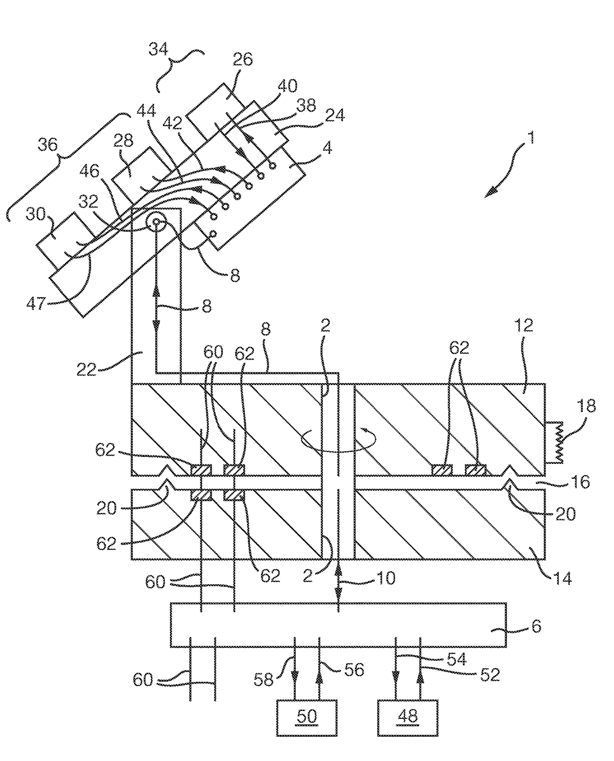
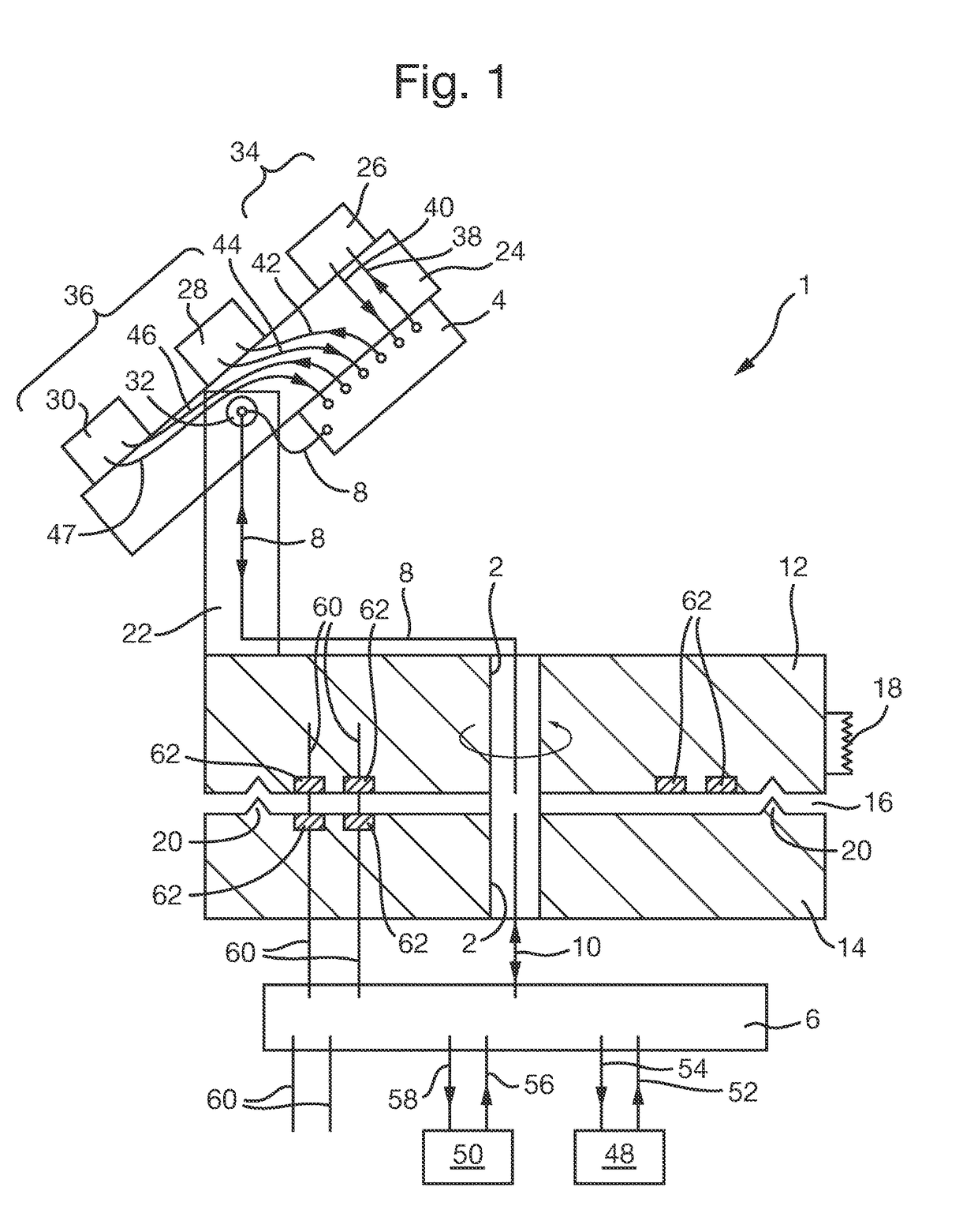
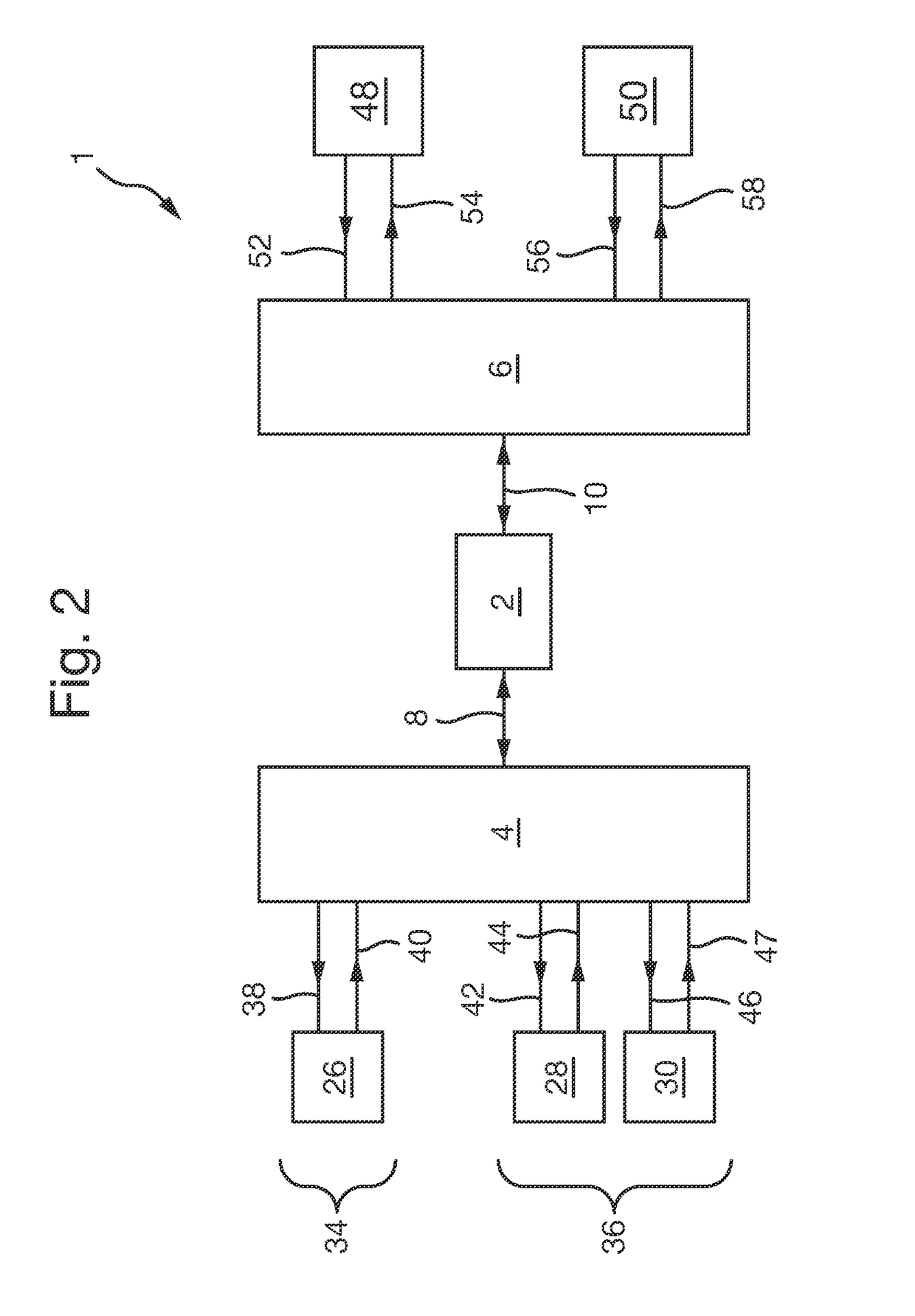
[0037]FIG. 1 is a schematic illustration (not to scale) of a first embodiment of an ORJ interface system 1. For convenience also presented is FIG. 2 which is a simplified block diagram illustration of the ORJ interface system 1, in which schematic mechanical details are omitted for ease of reference regarding the electrical and optical couplings present and which will be described in the following.

[0038]In the following description, the terminology “a rotating . . . ” and “a fixed . . . ” is used as a form of annotation for ease of reference to allow the reader to readily appreciate which elements in the particular embodiments described below are on the rotating side of the overall arrangement and which are on the fixed side. It will be appreciated that such terminology is merely used for identification purposes, and does not specify or imply any intrinsic rotation or otherwise (other than by virtue of being on the main rotating platform or not on it) of the particular element so id...


PUM


Abstract

A method and apparatus for operating an optical rotating joint (2); comprising: routing optical signals through an optical rotating joint (2) by using a first optical circulator (64) on a first side of the optical rotating joint (2) to receive an optical signal and direct the optical signal onward to a first side of the optical rotating joint (2), and using a second optical circulator (93) on a second side of the optical rotating joint (2) to receive the optical signal from the second side of the optical rotating joint (2) and direct it onwards. The signals may be sensor control signals or sensor output signals to / from a plurality of sensors (26, 28, 30), for example camera sensors. The apparatus may further comprise one or more wavelength division multiplexers (68, 94) and / or wavelength division demultiplexers (66, 95).

Description

FIELD OF THE INVENTION[0001]The present invention relates to apparatus and methods for use with optical rotating joints (also known as fibre optic rotary joints). The present invention relates in particular to, but is not limited to, apparatus and methods in which sensor output signals and sensor control signals are passed through an optical rotating joint.BACKGROUND[0002]The use of optical rotating joints (ORJs), also known as fibre optic rotary joints (FORJs), for transmission of an optical signal in a fibre-optic cable across an interface between two physical entities, where at least one of the physical entities is rotating, is known. One type of ORJ is a single channel single-mode ORJ, i.e. one in which optical signals are transmitted across the rotating interface from one fixed single-mode optical fibre to one rotating single-mode optical fibre.[0003]In some applications of ORJs, optical plural signals or channels are multiplexed, for example by time-division multiplexing or wa...

Claims


Application Information

Patent Timeline
Patent Type & Authority Patents(United States)
IPC IPC(8): G02B6/36H04B10/25H04J14/02H04Q11/00
CPCG02B6/3604H04B10/2504H04J14/02H04Q2011/0037H04Q11/0005G02B6/2746H04B10/25H04B10/25891
Inventor PESCOD, CHRISTOPHER RALPHNAWAZ, MOHAMMED
Owner BAE SYSTEMS PLC
Why Eureka
Try Eureka