Vehicle

a technology for vehicles and seats, applied in the field of vehicles, can solve the problems of increasing the widthwise length of the vehicle, reducing the space between the auxiliary pipes and the seat pipes, and unable to deliver satisfactory performance, etc., to achieve sufficient stroke and operating range, improve the layout flexibility of the arm connector, and increase the strength of the upper frame

Active Publication Date: 2017-11-14
YAMAHA MOTOR CO LTD
View PDF15 Cites 4 Cited by
  • Summary
  • Abstract
  • Description
  • Claims
  • Application Information

AI Technical Summary

Benefits of technology

[0008]Accordingly, preferred embodiments of the present invention provide a vehicle including shock absorbers that have a sufficient operating range and thus deliver desirable shock absorbing performance.
[0010]According to the preferred embodiment of the present invention described above, the distance between the first and second upper connections is preferably longer than the distance between the first and second lower connections. Thus, the connection frame widely supports the upper frame and increases the strength of the upper frame. The arm connector is disposed rightward of the left upper arm and leftward of the right upper arm. This prevents interference between the left upper arm and the arm connector when the left upper arm oscillates, and prevents interference between the right upper arm and the arm connector when the right upper arm oscillates, resulting in an improved layout flexibility of the arm connector particularly in the up-down direction of the vehicle. Because the arm connector is located at a low position, a wide space is provided between the arm connector and the upper frame. This enables the arrangement of the first upper end portion of the left shock absorber and the second upper end portion of the right shock absorber in the wide space provided between the arm connector and the upper frame. Consequently, the right and left shock absorbers are prevented from interfering with other members, while the right and left shock absorbers each have a sufficient stroke and operating range.
[0011]Various preferred embodiments of the present invention provide a vehicle including shock absorbers that have a sufficient operating range and thus deliver desirable shock-absorbing performance.

Problems solved by technology

Unfortunately, such an approach increases the widthwise length of the vehicle.
This disadvantageously reduces the space between the auxiliary pipes and the seat pipes.
If this space is small, the shock absorbers have a narrow operating range and thus cannot deliver satisfactory performance.

Method used


Image

  • Vehicle
  • Vehicle
  • Vehicle

Examples


Embodiment Construction

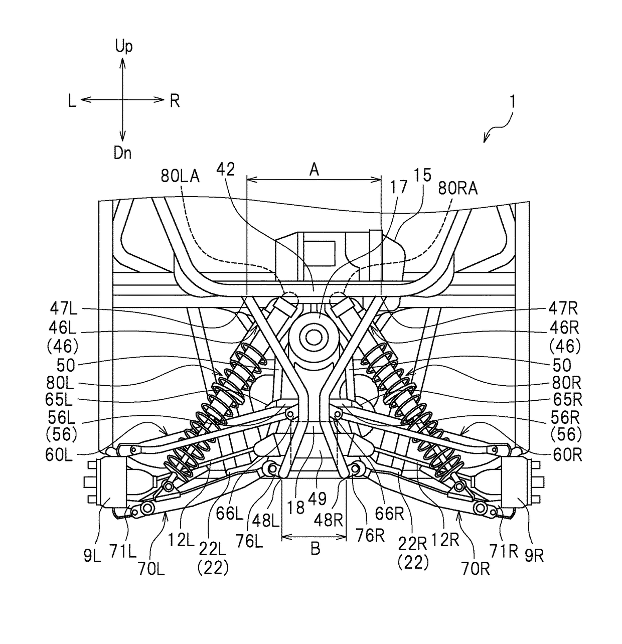
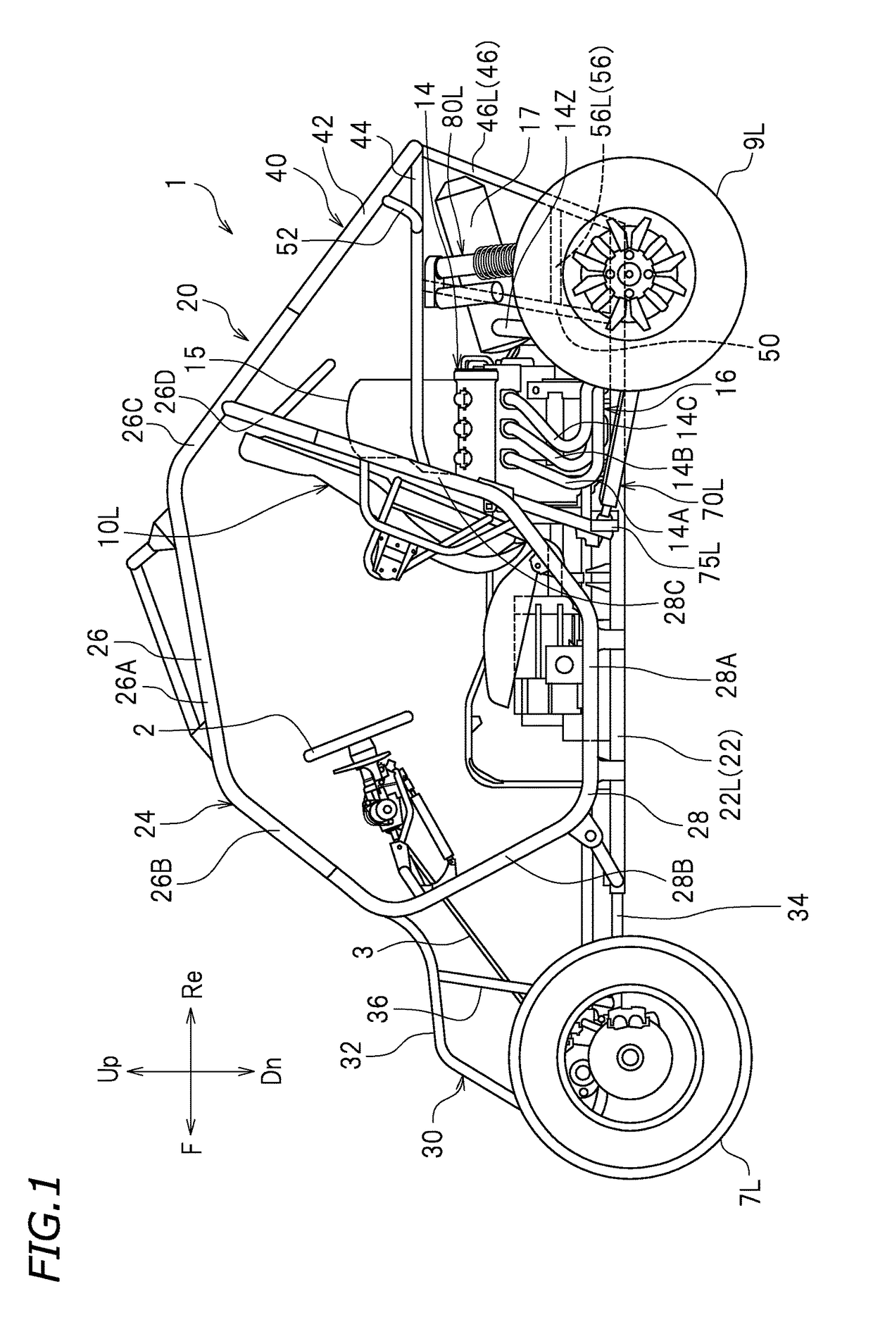
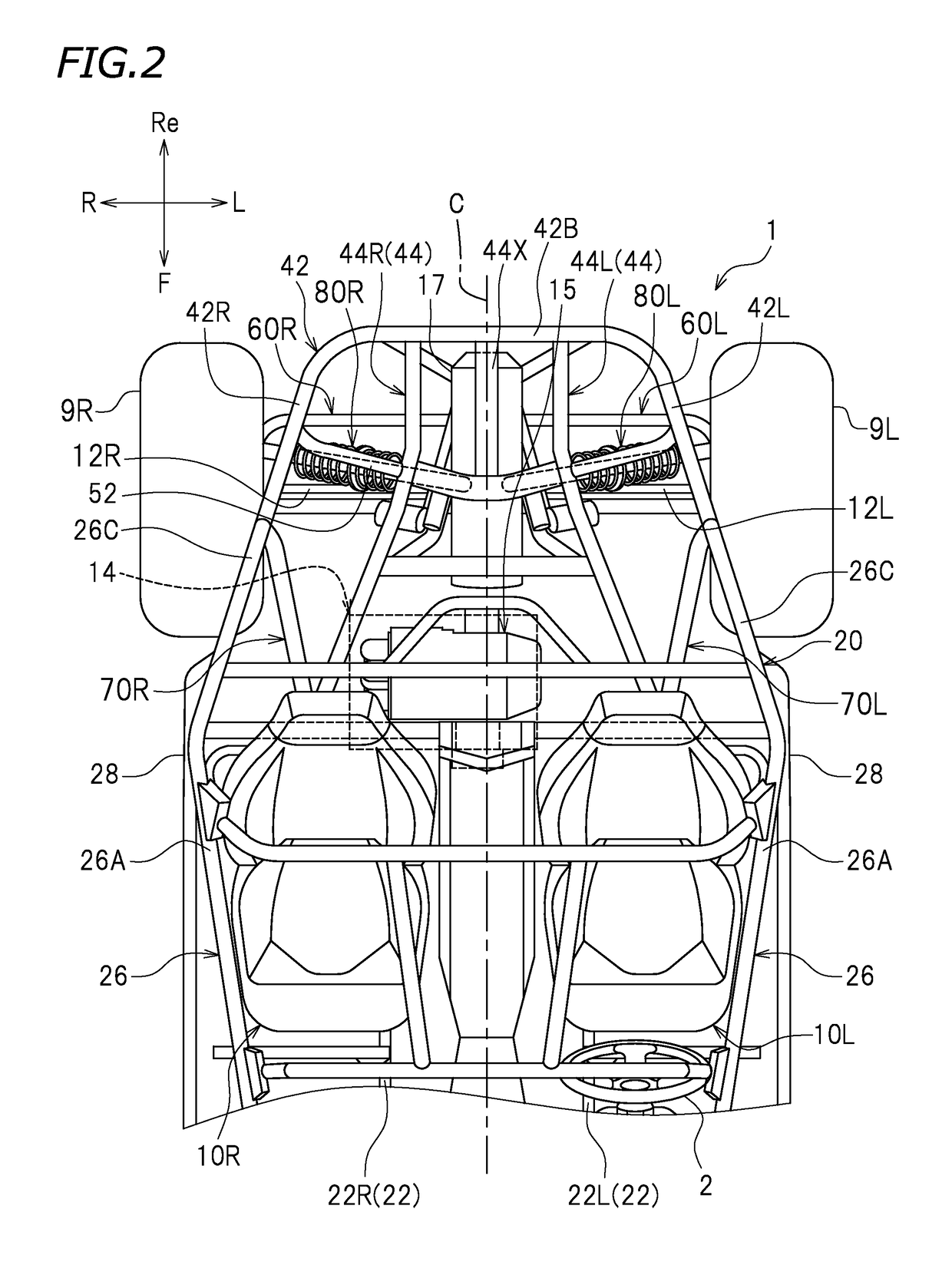
[0022]Hereinafter, preferred embodiments of the present invention will be described. As illustrated in FIG. 1, a vehicle according to the present preferred embodiment is, for example, a recreational off-highway vehicle (ROV) 1. The ROV 1 is suitable for traveling over rough terrain. The vehicle according to preferred embodiments of the present invention is not limited to an ROV, but may be an all-terrain vehicle (ATV) or other suitable vehicle, for example.

[0023]Unless otherwise noted, the terms “front”, “rear”, “right”, “left”, “up”, and “down” respectively refer to front, rear, right, left, up, and down with respect to a driver sitting on a left seat 10L of the ROV 1 in the following description. The terms “up” and “down” respectively refer to the vertically upward direction and the vertically downward direction when the ROV 1 is stationary on a horizontal plane. Reference signs “F”, “Re”, “R”, “L”, “Up”, and “Dn” in the drawings respectively represent front, rear, right, left, up...


PUM


Abstract

A recreational off-highway vehicle ROV includes a first connection subframe connected to a first rear subframe and a main frame, and an arm connector disposed rightward of a left upper arm and leftward of a right upper arm and supporting the right and left upper arms. A distance between first and second upper connections connecting the first rear subframe and the first connection subframe is longer than a distance between first and second lower connections connecting the main frame and the first connection subframe. A first upper end portion of a left shock absorber and a second upper end portion of a right shock absorber are disposed between the first and second upper connections in a rear view of the vehicle.

Description

[0001]This application claims priority to Patent Application No. 2014-261977 filed in Japan on Dec. 25, 2014, the entire contents of which are hereby incorporated by reference.BACKGROUND OF THE INVENTION[0002]1. Field of the Invention[0003]The present invention relates to vehicles suitable for traveling over rough terrain.[0004]2. Description of the Related Art[0005]Vehicles suitable for traveling over rough terrain are conventionally known. Included among such vehicles are an all-terrain vehicle (ATV) and a recreational off-highway vehicle (ROV). For example, U.S. Pat. No. 7,461,851 B2 discloses an ROV including rear wheels, a rear frame, upper arms, lower arms, and shock absorbers. The rear wheels are supported by the rear frame via the upper and lower arms. The shock absorbers are connected to the rear frame and the lower arms.[0006]Each shock absorber is arranged so that its upper end portion is disposed outward of the rear frame. Such an arrangement reduces the widthwise distan...

Claims


Application Information

Patent Timeline
Patent Type & Authority Patents(United States)
IPC IPC(8): B60K5/00B60G13/00B60K17/16B60G3/20B60G7/00B60K13/04
CPCB60G13/005B60G7/001B60K5/00B60K17/165B60G3/20B60Y2200/20B60G2200/144B60G2206/10B60G2206/124B60G2300/07B60G2300/124B60G2300/13B60K13/04B60K2005/003B60Y2200/124
Inventor SUZUKI, YASUHIROKUBO, MASAYUKITAKATA, KAZUNARI
Owner YAMAHA MOTOR CO LTD
Why Eureka
Try Eureka