
Mounting structure of exterior belt

a technology for mounting structures and exterior belts, which is applied in the direction of doors, transportation and packaging, mechanical equipment, etc., can solve the problems of forming gaps between the end piece and the panel in a vertical and/or lateral direction, poor a substantial period of time for assembling the exterior belt. , to achieve the effect of improving the external appearance of the exterior belt, reducing production costs, and simplifying assembly

Active Publication Date: 2017-11-21
HYUNDAI MOTOR CO LTD
View PDF21 Cites 0 Cited by
  • Summary
  • Abstract
  • Description
  • Claims
  • Application Information

AI Technical Summary

Benefits of technology

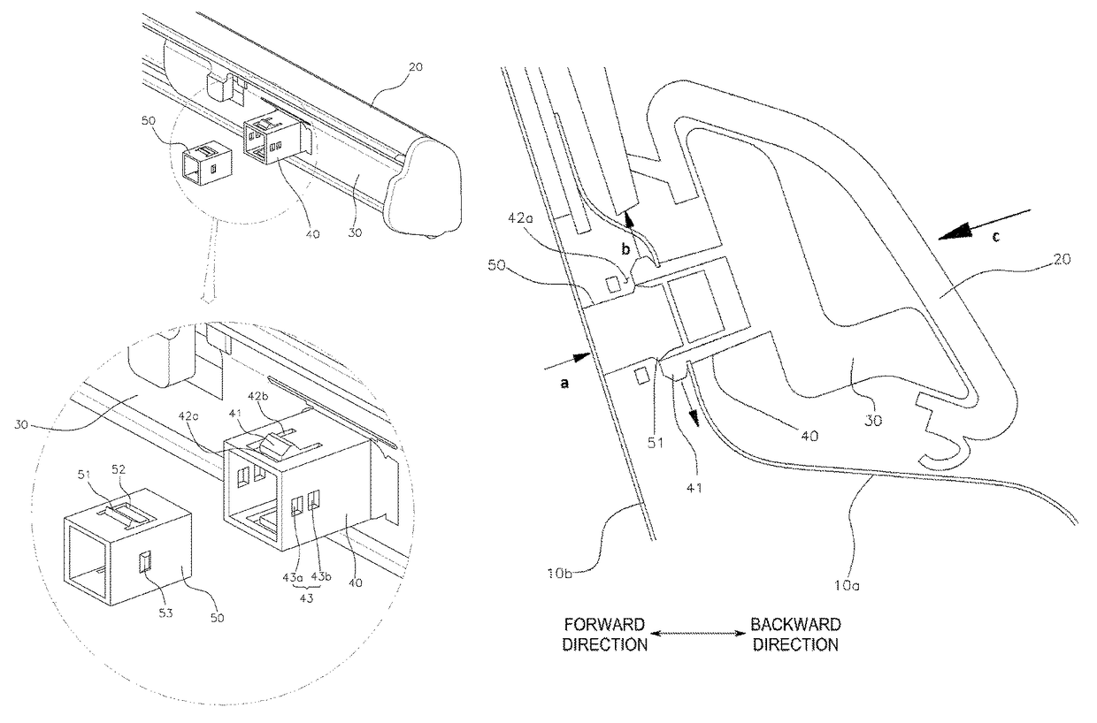
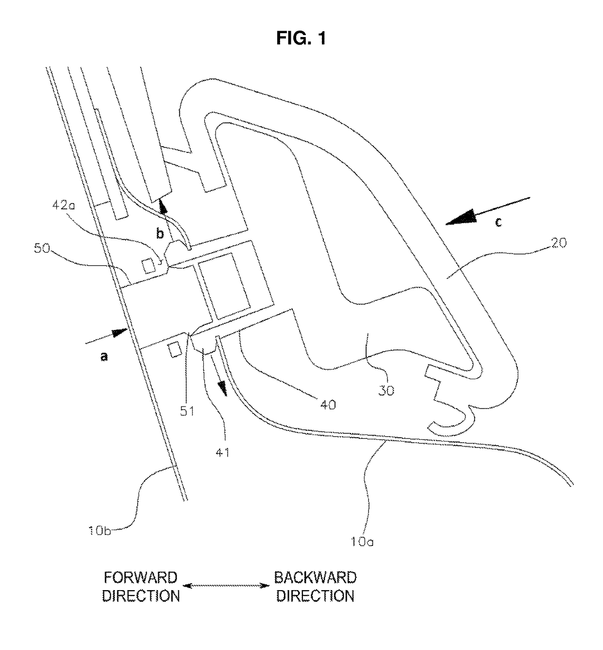
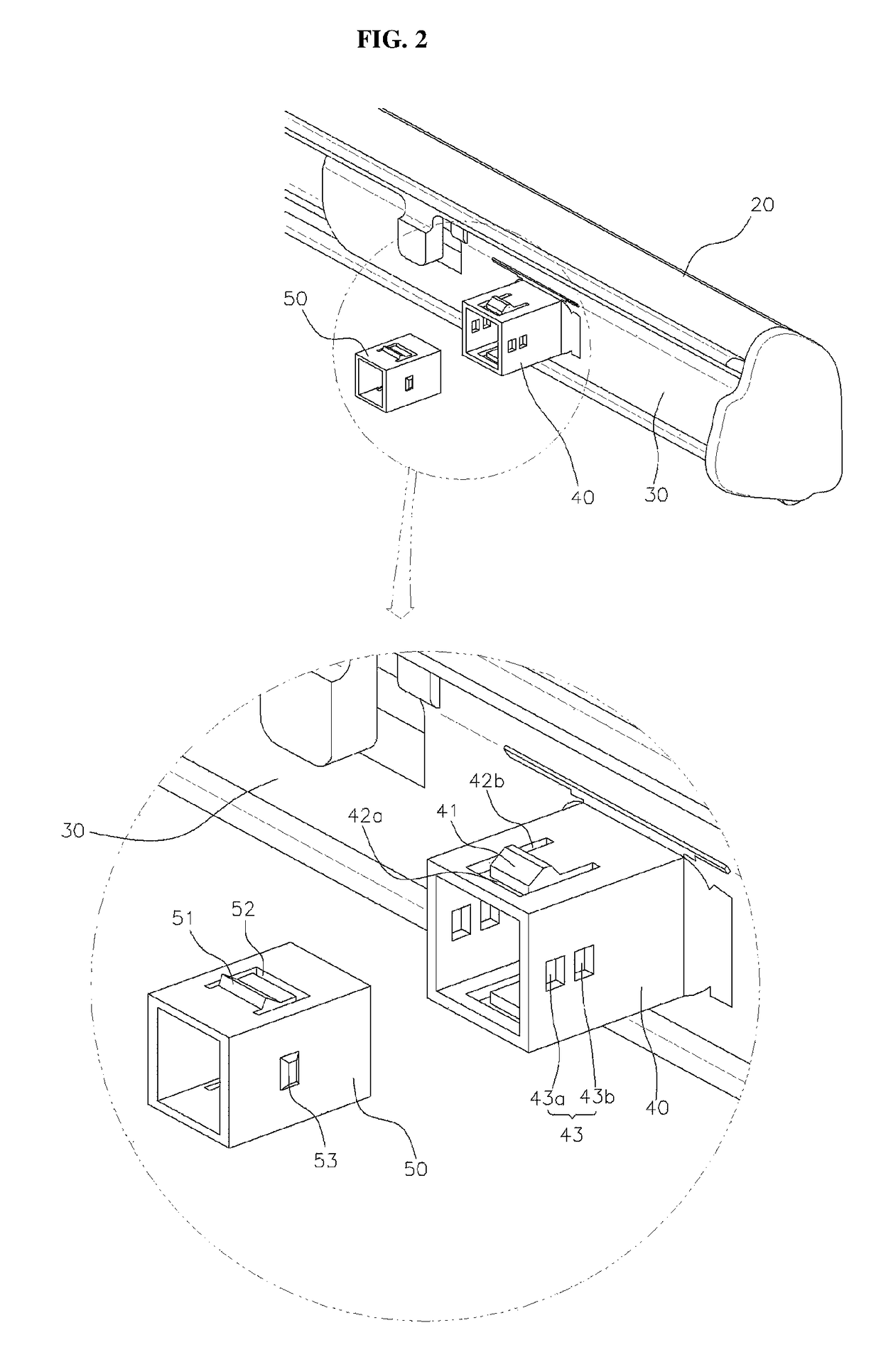
The present invention provides a mounting structure for an exterior belt that improves its appearance while reducing production costs. The structure also simplifies assembly, prevents gaps, and prevents damage from belt removal due to the absence of screws. The first clip has a second slit that allows for elastic deformation and an inclined surface at the front and rear sides of the protrusion. The second clip has a third slit that facilitates elastic deformation when fitting into the first clip. Both clips have a square pipe shape with two lateral side surfaces between the upper and lower surfaces. The protrusion is formed on the upper and lower surfaces of the first clip, while the protruding portion is formed on the upper and lower surfaces of the second clip.

Problems solved by technology

However, the exterior belt may have a poor appearance due to the exposed screw, and it may take a substantial period of time to assemble the exterior belt.
However, a gap may be formed between the end piece and the panel in a vertical direction and / or a lateral direction due to the relatively weak fastening force (upon external impact etc.).
Moreover, since the clip 4 may be damaged when the end piece is removed if necessary, costs for replacement thereof may be increased.

Method used


Image

  • Mounting structure of exterior belt
  • Mounting structure of exterior belt
  • Mounting structure of exterior belt

Examples


Embodiment Construction

[0019]It is understood that the term“vehicle” or “vehicular” or other similar term as used herein is inclusive of motor vehicles in general such as passenger automobiles including sports utility vehicles (SUV), buses, trucks, various commercial vehicles, watercraft including a variety of boats and ships, aircraft, and the like, and includes hybrid vehicles, electric vehicles, combustion, plug-in hybrid electric vehicles, hydrogen-powered vehicles and other alternative fuel vehicles (e.g. fuels derived from resources other than petroleum).

[0020]The terminology used herein is for the purpose of describing particular embodiments only and is not intended to be limiting of the invention. As used herein, the singular forms “a”, “an” and “the” are intended to include the plural forms as well, unless the context clearly indicates otherwise. It will be further understood that the terms “comprises” and / or “comprising,” when used in this specification, specify the presence of stated features, ...


PUM


Abstract

A mounting structure of an exterior belt is provided. The structure includes a frame and an end piece, and a door is coupled with an outer panel having a mounting aperture formed exterior an inner panel. Additionally, a first clip is formed at the end piece, and has a protrusion and a first slit formed at a front of the protrusion. A second clip is slidably coupled to the first clip and has a protruding portion. The second clip is inserted into the mounting aperture when the protruding portion is fitted into the first slit, and when one end thereof comes into contact with the inner panel when the protrusion is inserted into the mounting aperture, the other end thereof is moved backward toward the first clip, to restrict the first clip in the mounting aperture.

Description

CROSS-REFERENCE TO RELATED APPLICATION[0001]This application claims the priority benefit of Korean Patent Application No. 10-2016-0003467, filed on Jan. 12, 2016 in the Korean Intellectual Property Office, the disclosure of which is incorporated herein by reference.BACKGROUND[0002]Field of the Invention[0003]The present invention relates to a structure for mounting an exterior belt to a vehicle door, and more particularly to a mounting structure of an exterior belt, which reduces production costs, prevents the formation of a gap, and prevents damage when an exterior belt is mounted or removed.[0004]Description of the Related Art[0005]As illustrated in FIG. 1 of the related art, an exterior belt is mounted to an outer panel 1a of a vehicle door 1 to be adjacent to a window glass which moves vertically within the vehicle door. The exterior belt improves a vehicle design, and is mounted together with or independently of a weather strip to prevent foreign substances and noise from being...

Claims


Application Information

Patent Timeline
Patent Type & Authority Patents(United States)
IPC IPC(8): B60R13/02F16B5/12B60J5/04B60R13/06B60J10/36
CPCB60J5/0411F16B5/126B60R13/06B60J10/36B60R13/04F16B5/128F16B21/075F16B21/086
Inventor NAM, YONG-HYUN
Owner HYUNDAI MOTOR CO LTD
Learn More