Supercharge Your Innovation With Domain-Expert AI Agents!

Planar-ended ripple spring and hardened stator bar armor

a ripple spring and stator bar technology, applied in the field of stators, can solve the problems of increasing the abrasion-related damage to both the spring and the armored stator bar surface, reducing service longevity, and costing the downtim

Active Publication Date: 2017-11-21
GENERAL ELECTRIC CO
View PDF27 Cites 0 Cited by
  • Summary
  • Abstract
  • Description
  • Claims
  • Application Information

AI Technical Summary

Benefits of technology

The present invention aims to address certain issues that were previously present. Its technical effects can be viewed as solving the problems that previously existed.

Problems solved by technology

Consequently, when a ripple spring wears, the lateral forces of the stator bar may increase the abrasion-related damage to both the spring and armored stator bar surfaces.
The phenomenon may reduce the service longevity of a designed stator winding, causing an unscheduled outage, and potentially resulting in a down-time cost.
Another abrasion problem may occur when an uneven ripple finish at the edge or end of a side ripple spring wears against the armored glass layer of the stator bar.
In this case, the reduced ground wall insulation thickness may increase the frequency and need for repairs or replacement.

Method used


Image

  • Planar-ended ripple spring and hardened stator bar armor
  • Planar-ended ripple spring and hardened stator bar armor
  • Planar-ended ripple spring and hardened stator bar armor

Examples


Embodiment Construction

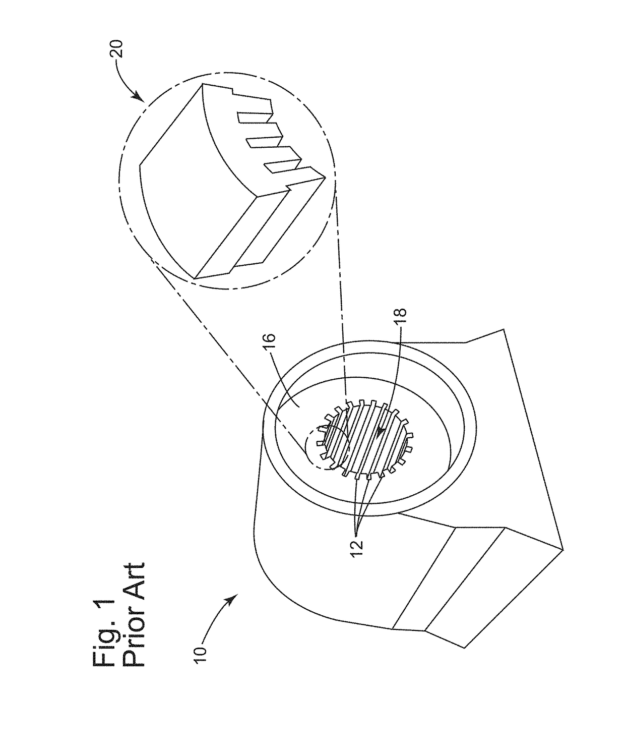
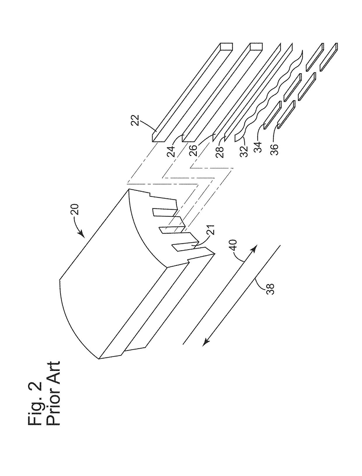
[0022]FIG. 1 is a perspective end view of an electric machine 10. Electric machine 10 includes a core 16 having a plurality of stator slots 12 to accommodate a winding to generate an electro-magnetic flux. Stator slots 12 are configured to accommodate stator windings to be positioned in the stator slots defined around an inner circumference of core 16 (also referred to as the stator core). The stator windings may be formed from a plurality of flat bar conductors or stator bars that are coupled together to form a predetermined winding path. In one aspect of the invention, the stator bars are fabricated from roebelling the rectangular copper strand package. A rotor (not shown) may be disposed within an opening 18 in stator core 16 where an air or coolant gap is defined between the rotor and stator core 16. A partial, exploded view of the stator is illustrated by reference numeral 20 that is described in detail with reference to FIG. 2. Electrical machine 10 may be any electrical rotat...


PUM


Abstract

A ripple spring includes a body including a central portion having a substantially sinusoidal shaped surface and a substantially planar end portion extending from each end of the central portion. A stator bar may include an armor layer including a novalac epoxy resin impregnated glass composite.

Description

CROSS-REFERENCE TO RELATED APPLICATIONS[0001]This application claims priority to currently U.S. Patent Provisional Application No. 62 / 043,187 filed on Aug. 28, 2014. The application identified above is incorporated herein by reference in its entirety for all that it contains in order to provide continuity of disclosure.BACKGROUND OF THE INVENTION[0002]The disclosure relates generally to stators, and more particularly, to a ripple spring having substantially planar end portions to reduce the tendency of abrasion-induced stator winding damage, and a stator bar with a heat resistant and hardened armor layer.[0003]Armature windings, also known as stator bars or windings, are routinely inspected in electrical power generators to verify their operation during scheduled outage. In some generators, a stator yoke in the generator surrounds an armature core and partially encloses the armature windings. The stator windings are formed from a plurality of copper conductors that are wound in the ...

Claims


Application Information

Patent Timeline
Patent Type & Authority Patents(United States)
IPC IPC(8): H02K3/30F16F1/18
CPCF16F1/185H02K3/30
Inventor ARRAO, ANTHONY SALVATOREXU, JAMES JUN
Owner GENERAL ELECTRIC CO
Features
  • R&D
  • Intellectual Property
  • Life Sciences
  • Materials
  • Tech Scout
  • Unparalleled Data Quality
  • Higher Quality Content
  • 60% Fewer Hallucinations
Learn More