Lightweight Blast Mitigating Composite Panel

a composite panel and light weight technology, applied in the field of protective panels, can solve the problems of increasing terrorist threats to public transportation, limiting the ability of uhmwpe fibers to delocalize, etc., and achieve the effects of increasing dynamic stiffness, high strength, and increasing adhesion

Active Publication Date: 2011-02-24
BATTELLE MEMORIAL INST
View PDF6 Cites 21 Cited by
  • Summary
  • Abstract
  • Description
  • Claims
  • Application Information

AI Technical Summary

Benefits of technology

[0009]The present invention is directed to a lightweight blast mitigating composite panel. More specifically, a composite panel includes multiple layers incorporating ultra high molecular weight polyethylene (UHMWPE) fibers as a primary strength component, a honeycomb layer, flame resistant thermoset adhesive layers applied on either side of the UHMWPE layer, and a fiber reinforcing layer applied on either side of the flame resistant thermoset layers. These composite layers form a core which is then encased in an outer fiberglass shell. The flame resistant thermoset adhesive layers provide for increased adhesion between the UHMWPE core and the high strength reinforcing fibers. The overall combined layerin

Problems solved by technology

A limiting factor of such armors is the ability of the UHMWPE fibers to delocalize or disperse a blast load over the matrix.
It is an unfortunate fact that terrorist threats to public

Method used


Image

  • Lightweight Blast Mitigating Composite Panel
  • Lightweight Blast Mitigating Composite Panel
  • Lightweight Blast Mitigating Composite Panel

Examples


Embodiment Construction

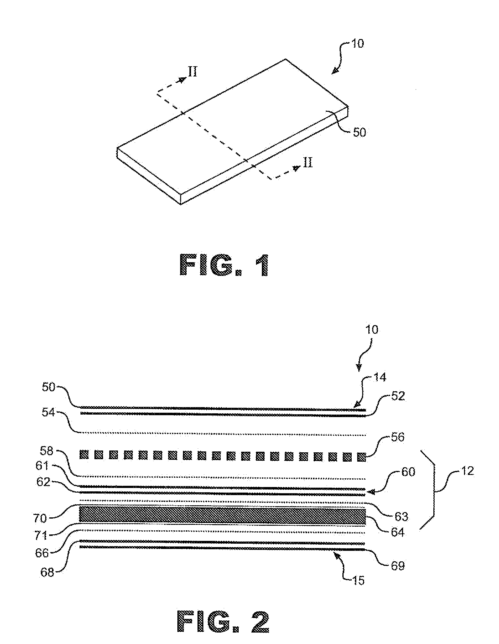
[0016]With initial reference to FIG. 1, a lightweight blast mitigating composite panel is generally indicated at 10. As will be detailed more fully below, panel 10 is constructed in a manner which provides for enhanced blast absorption, suppression and mitigation capabilities verses known composite panels employed for similar purposes. In general, panel 10 has various potential uses, including military, law enforcement, transportation and storm management fields.

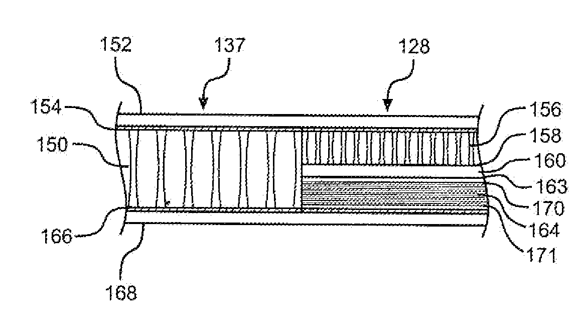
[0017]Turning to FIG. 2, panel 10 incorporates ultra high molecular weight polyethylene (UHMWPE) fibers within a matrix to form a core 12 that is subsequently encased by first and second outer shells indicated at 14 and 15. Core 12 and shells 14 and 15 may be further surrounded by a protective sleeve or case (not shown).

[0018]More specifically, as depicted in FIG. 2, composite panel 10 includes outer shell 14 which is preferably comprised of reinforcing layers 50 and 52, a first flame-resistant adhesive layer 54, an intermed...


PUM

PropertyMeasurementUnit
Thicknessaaaaaaaaaa
Electrical resistanceaaaaaaaaaa
Molecular weightaaaaaaaaaa

Abstract

Lightweight blast mitigating composite panels (10) include a first glass composite shell (14; 152), an intermediate, preferably honeycomb layer (56; 156), a reinforcing layer (60; 160), an ultra high molecular weight polyethylene fiber (UHMWPE) layer (64; 164) and a second glass composite shell (15; 168) adhered together with fire resistant adhesive layers (54; 58, 63, 66; 154, 158, 163, 166). The UHMWPE layer (64; 164) includes top and bottom coatings (70, 71) of fire resistant thermoset plastic preferably in the form of a paste. The panels (10) have use in a wide range of applications including in a blast mitigating overhead storage bin (100). The storage bin (100) includes a main body portion (133) defining a storage area formed from composite unarmored and armored panel segments (137, 138; 128-132). The unarmored and armored panel segments (137, 138; 128-132) share first and second shells (14, 15) to form an integral main body portion, with the armored panel segments (128-132) providing blast protection between the storage area and a wall (125) of an airplane cabin (120).

Description

CROSS-REFERENCE TO RELATED APPLICATIONS[0001]The present invention claims the benefit of U.S. Provisional Patent Application Ser. No. 61 / 071,516, filed May 2, 2008, entitled “Aircraft Overhead Storage Bin” and U.S. Provisional Patent Application Ser. No. 61 / 071,517, filed May 2, 2008 entitled “Lightweight Blast Mitigating Composite Panel”.STATEMENT REGARDING FEDERALLY SPONSORED RESEARCH OR DEVELOPMENT[0002]The present invention was developed under TSA / TSL Contract No. DTFACT-03-C-00042. Therefore, the U.S. Government has certain rights to the invention.BACKGROUND OF THE INVENTION[0003]1. Field of the Invention[0004]The present invention pertains to the art of protective panels and, more specifically, to lightweight blast mitigating composite panels.[0005]2. Discussion of the Prior Art[0006]Blast mitigation can be achieved by numerous methods including the use of structural elements such as composite armor. In general, composite armor comprises a system of materials in which ultra hi...

Claims


Application Information

Patent Timeline
IPC IPC(8): B64D7/00F41H5/04B65D25/00B32B17/06B32B7/12B32B3/12
CPCF42D5/045F41H5/04Y10T428/24132Y10T428/24149
Inventor POLLOCK, CLARENCE E.PERRY, MARK J.BUSH, JOHN R.SEIDT, JEREMY D.FISHER, MICHAEL L.
Owner BATTELLE MEMORIAL INST
Why Eureka
Try Eureka