
Transparent glass scintillators, methods of making same and devices using same

a scintillator and transparent glass technology, applied in the field of transparent glass composites, can solve the problems of inapplicability to other forms of nuclear radiation detection, inapplicability to non-ideal conditions, and the resolution of solid-state detectors that exceed the resolution of inorganic crystals, but so far are limited in size or require operation

Active Publication Date: 2014-06-19
GEORGIA TECH RES CORP
View PDF2 Cites 21 Cited by
  • Summary
  • Abstract
  • Description
  • Claims
  • Application Information

AI Technical Summary

Benefits of technology

The patent describes transparent glass composites that can detect nuclear radiation using nanoparticles distributed in the glass body. The glass composites have a matrix metal compound and a dopant metal compound, which combine to form a glass body with nanoparticles distributed throughout. The nanoparticles can have a refractive index that differs from the refractive index of the glass body. The glass composites can interact with nuclear radiation and scintillate, providing a means for detection. The method involves heating a mixture of matrix metal compound, dopant metal compound, and inorganic glass former, and cooling it to solidify the glass body. The nanoparticles can have a size of 1 to 50 nm and can have a refractive index that differs from the refractive index of the glass body. The technical effect is the creation of a transparent glass composite with improved detection of nuclear radiation.

Problems solved by technology

However, they are plagued by several substantial weaknesses that make them difficult or inapplicable to use in non-ideal conditions, e.g. in the field or in a port.
These weaknesses include instability due to humidity, mechanical shock, and temperature fluctuations among other issues.
Moreover, while materials such as NaI:Tl are excellent for gamma ray detection, they are often inapplicable for detection other forms of nuclear radiation.
As an alternative, solid-state detectors far exceed the resolution of these inorganic crystals but so far are limited in size or require operation at very low temperature.
However, few studies have been conducted in terms of gamma-ray spectroscopy applications.

Method used


Image

  • Transparent glass scintillators, methods of making same and devices using same
  • Transparent glass scintillators, methods of making same and devices using same
  • Transparent glass scintillators, methods of making same and devices using same

Examples


example 1

Cerium Doped Gadolinium Halide

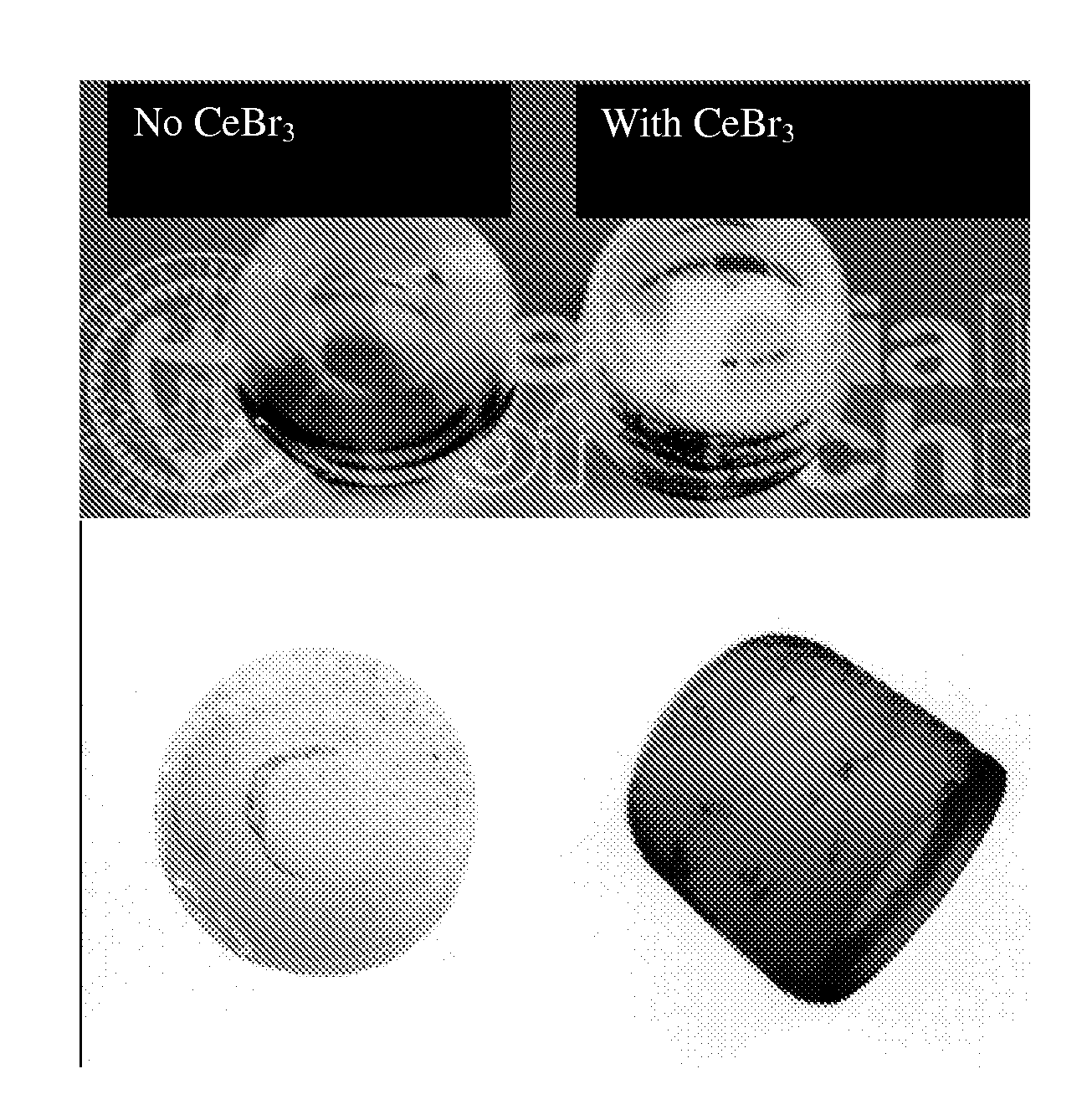
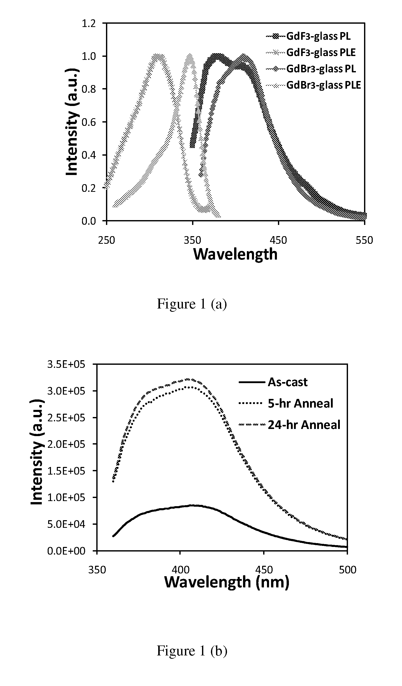
[0084]Powders of high-purity grade gadolinium halide and cerium halide were mixed with conventional glass forming chemicals: SiO2, Al2O3 and NaF at a molar ratio of 50SiO2-16Al2O3-19NaF-13GdX3-2CeX3. (X can be fluoride or bromide). Each batch weighed from 10 to 40 grams and was contained in a graphite plate covered alumina crucible. Samples were heated in an argon atmosphere at 200° C. for 1 hour and then melted at 1450° C. for 1 hour to form a homogenous liquid mixture. The samples were then quenched to room temperature by directly casting the melt into a preheated graphite mold of 2.5 cm in diameter. The cast precursor glass samples were subsequently annealed at temperatures between 450° C. and 750° C. to release thermal stress and promote nanocrystal precipitation.

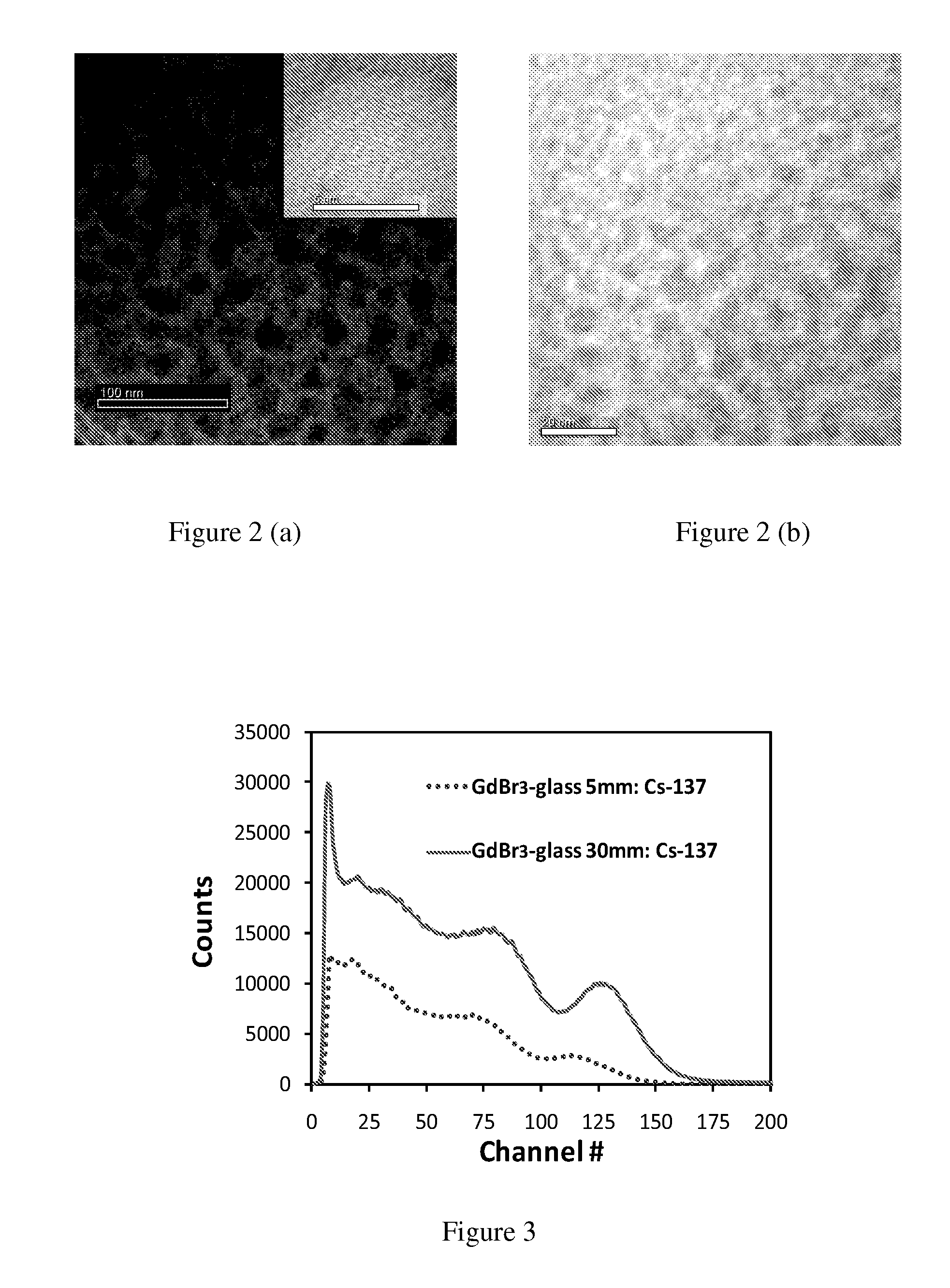
[0085]Cylindrical glass composite samples with different halide compositions were fabricated and characterized in this work. Photoluminescence (PL) and Photoluminescence Excitation (PLE) sp...

example 2

General Method for Preparing Silicate Glasses of Cerium Doped Gadoliuium Bromide

[0094]The same basic method was used to synthesize all glass systems with a general composition of SiO2—Al2O3—NaF—GdBr3—CeBr3. The following constituent powders available from Alfa Aesar were used for the glass synthesis: 2 μm SiO2 (99.5%), 3 μm gamma-phase Al2O3 (99.97%), NaF, GdBr3.XH2O (99.99%), and CeBr3.XH2O (99.999%). A “base glass” composition of 46SiO2-15Al2O3-17NaF-17GdBr3-2CeBr3 was used as a starting point for all investigations. Precise quantities of GdBr3 and CeBr3 were varied to observe the effects of different scintillating material concentration. Precursor powders were thoroughly mixed with a mortar and pestle and then packed into a 50 mL Al2O3 crucible, with powder batch sizes ranging from 50-130 g. The crucible was covered with a one-quarter inch thick graphite plate and placed in a high temperature muffle furnace. Additional crucibles filled with carbon powder and BaBr2 were also place...

example 3

Europium Doped Calcium Fluoride

[0118]A glass with the molar composition 45SiO2-20Al2O3-10CaO-25CaF2-0.1Eu2O3 (or EuF2) was prepared. Reagent grade SiO2, Al2O3, CaO, CaF2, and Eu2O3 (or EuF2) were used as starting materials. The batch was placed in a platinum crucible and melted at 1400° C. for 2 h. To obtain the europium ions in the divalent state, carbon black powders were placed beside the crucible during the glass melting process. However, weak blue and strong red luminescence was observed from the prepared glass and glass composite samples, indicating most of the Eu ions were oxidized into Eu3+ states. The melt was cast onto a preheated, stainless steel plate, and subsequently annealed and cooled to room temperature. Glass composite was fabricated by heat treating the glass at 760 C for 3 h. The glass composite maintained a high transparency in the visible region. Luminescence spectra under UV excitation for the glass composite are shown in FIG. 19. The observed red emission pea...


PUM

PropertyMeasurementUnit
sizeaaaaaaaaaa
sizeaaaaaaaaaa
sizeaaaaaaaaaa

Abstract

Compositions and methods are described for transparent glass composite having nanoparticles therein that scintillate in the presence of nuclear radiation, particularly gamma rays, but also x-rays, alpha particles, beta particles, and neutrons. The transparent glass composites can be prepared by a melt / cool process to produce the transparent glass composite. The wavelength of light emitted by the transparent glass composite can be tailored based on the materials used to make the glass composite. A detector that utilizes the transparent glass composite can measure nuclear radiation from numerous sources.

Description

RELATED APPLICATIONS[0001]This application claims, under 35 U.S.C. §119(e), the benefit of U.S. Provisional Patent Application Ser. No. 61 / 468,823, filed 29 Mar. 2011, the entire contents and substance of which are hereby incorporated by reference as if fully set forth below.FEDERALLY SPONSORED RESEARCH STATEMENT[0002]The invention described in this patent application was made with Government support under Grant Award No. 2008-DN-077-ARI015-02 from the U.S. Department of Homeland Security. The Government has certain rights in the invention described in this patent application.TECHNICAL FIELD[0003]The various embodiments of the present disclosure relate generally to transparent glass composites for use as scintillators for detecting and measuring radiation products from decaying radioactive nuclei, including gamma rays, x-rays, alpha particles, beta particles, neutrons, and the like. More particularly, various embodiments of the present disclosure are directed toward glass composites...

Claims


Application Information

Patent Timeline
Patent Type & Authority Applications(United States)
IPC IPC(8): G01T1/20G01T1/208G01T3/06
CPCG01T1/2002G01T1/2006G01T3/06G01T1/208G01T1/2018C03C4/12C03C3/062C03C3/064C03C3/068C03C10/16G01T1/20187
Inventor KANG, ZHITAOWAGNER, BRENT KARLNADLER, JASON HAYESROSSON, ROBERTKAHN, BERNDBARTA, MEREDITH BROOKE
Owner GEORGIA TECH RES CORP
Learn More