Blower device

a blower and fan technology, applied in the direction of machines/engines, liquid fuel engines, transportation and packaging, etc., can solve the problems of uneven flow direction of the fan in the circumferential direction, affecting the flow rate of air blown out of the outer circumference of the fan, and affecting the flow rate of air blown out of the fan. , to achieve the effect of reducing the rotational nois

Active Publication Date: 2017-11-28
DENSO CORP
View PDF22 Cites 7 Cited by
  • Summary
  • Abstract
  • Description
  • Claims
  • Application Information

AI Technical Summary

Benefits of technology

[0008]In consideration of the above-described points, it is an objective of the present disclosure to provide a blower device including a fan shroud capable of reducing rotational noise.
[0011]According to the first aspect of the present disclosure, an air flow drawn along the protruding end part can be provided. A flow rate of the air drawn into the fan from the protruding end part can be increased, and flows of air into the fan can be oriented toward a center of the fan and be even in the circumferential direction. The inflow direction and the air inflow rate can be made to be more even in the whole circumference of the fan. Therefore, the blower device including the fan shroud capable of reducing the rotational noise can be provided.
[0012]According to a second aspect of the present disclosure, the short end part may be the shortest part in distance to the outer circumference in the fan of the outer end portion of the fan shroud. In this case, the protruding end part is formed at a position advanced in the rotational direction of the fan from the short end part that is most likely to cause the rotational noise. Thus, an air flow rate toward the outer circumference of the fan can be increased effectively. Moreover, since the protruding end part restricts increase of interference between the blades of the fan and the inflow air at the position advanced from the short end part in the rotational direction of the fan, the air inflow directions toward the fan also are oriented toward the center of the fan and become even in the circumferential direction. Hence, even when the number or the size of the protruding end parts provided in the fan shroud is reduced, the blower device capable of reducing the rotational noise effectively can be provided.
[0013]According to a third aspect of the present disclosure, the protruding end part may include an inner wall surface having a curved shape on a side toward the fan. In this case, when an air is drawn from the front into an inner side of the protruding end part, an air flow along the curved shape of the inner wall surface of the protruding end part can be provided. Thus, the drawn air can be introduced into the outer circumference of the fan smoothly. Accordingly, a flow rate of air introduced into the outer circumference of the fan via the protruding end part can be increased effectively. The correction of unevenness in inflow rate into the fan can be facilitated, and drastic reduction of the rotational noise can be achieved.
[0016]According to the fourth aspect of the present disclosure, the fan shroud includes the shield plate located at the position shifted from the short end part in the rotational direction of the fan and on the downstream side of the fan in the flow direction of the drawn air. By an effect of the shield plate to restrict the blown air, a flow rate of air blown out of the fan can be limited at the position advanced from the short end part in the rotational direction of the fan. According to the reduction of the flow rate of the blown air by the shield plate, the flow rate of air blown out of the outer circumference of the fan can be made to be more even, and the flow rate of the blown air in the circumferential direction can be further balanced. Therefore, the blower device including the fan shroud capable of reducing the rotational noise can be provided. Additionally, according to the blower device, the rotational noise can be reduced without increase in size such as height dimension of the fan shroud.
[0017]According to a fifth aspect of the present disclosure, the short end part may be the shortest part in distance to the outer circumference of the fan in the outer end portion of the fan shroud. In this case, the shield plate is provided on the downstream of the fan and at a position shifted in the rotational direction of the fan from the short end part that is most likely to cause the rotational noise. Thus, in this position, a flow rate of air blown out of the outer circumference of the fan can be decreased effectively. Hence, even when the number or the size of the shield plates formed in the fan shroud is reduced, the rotational noise can be reduced effectively. As long as the rotational noise can be reduced, the number and the size of the shield plates can be restricted. Therefore, a flow resistance on the downstream side of the fan can be limited.

Problems solved by technology

Thus, the flow rate of the air drawn into the outer circumference of the fan may be low in a part of the whole outer circumference of the fan, and the flow direction toward the fan may also become uneven in a circumferential direction.
These may cause so-called rotational noise that is noise associated with rotation of the fan.
The rotational noise increases remarkably due to an interference phenomenon between a high-speed rotating body and an ambient air, and the rotational noise has a single frequency component and an especially high sound pressure.

Method used


Image

  • Blower device
  • Blower device
  • Blower device

Examples


first embodiment

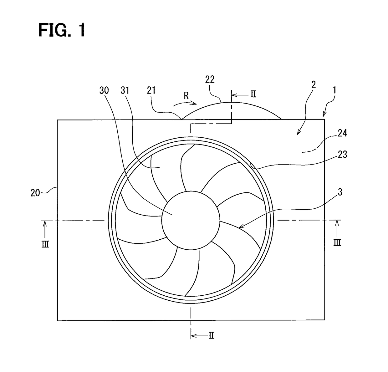
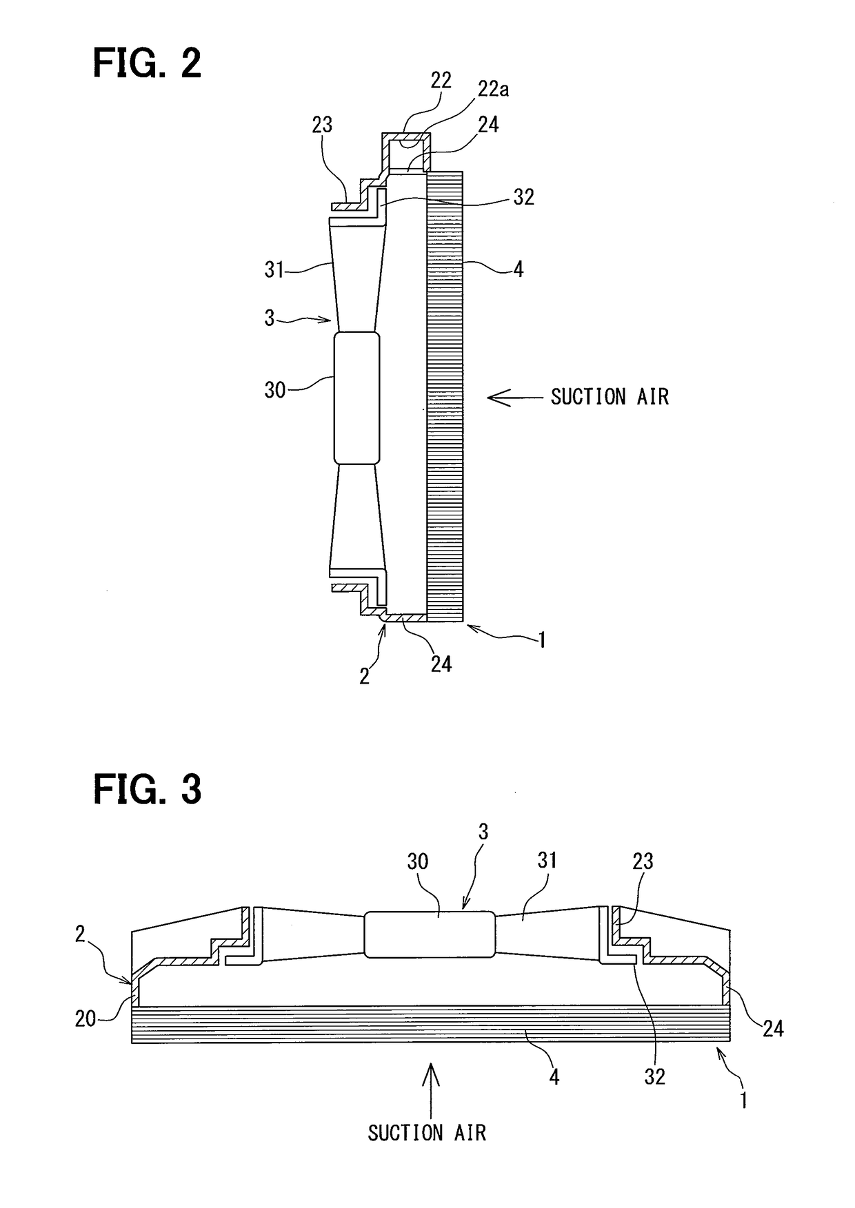
[0029]A blower device 1 of a first embodiment of the present disclosure will be described with reference to FIGS. 1 to 4. In the first embodiment, a device will be described as an example of the blower device, and the device conveys air to a radiator that is disposed in a vehicle to cool an engine, for example. FIG. 1 is a back view illustrating the blower device 1 of the first embodiment. FIG. 2 is a sectional view showing a part of a fan shroud 2 when a sectional surface taken along a line II-II of FIG. 1 is viewed in an arrow direction. FIG. 3 is a sectional view showing a part of the fan shroud 2 when a sectional surface taken along a line III-III of FIG. 1 is viewed in an arrow direction. In FIGS. 1 to 3, a motor and a motor stay which drive a fan 3 to rotate are not shown. An arrow in the drawings shows a flow direction of air suctioned by the blower device 1.

[0030]The blower device 1 includes the fan 3 that is single and an axial flow type, and the fan shroud 2 supporting the...

second embodiment

[0047]A second embodiment is an embodiment changed in configuration of a blower device 1A from the first embodiment. FIG. 5 is a back view illustrating the blower device 1A of the second embodiment. FIG. 6 is a sectional view showing a part of a fan shroud 2A when a sectional surface taken along a line VI-VI of FIG. 5 is viewed in an arrow direction.

[0048]As shown in FIGS. 5 and 6, the blower device 1A is different from the blower device 1 of the first embodiment in that the fan shroud 2A includes a protruding end part 22A on an opposite side of an outer end portion of the fan shroud 2A from a protruding end part 22. A configuration that will not be explained is similar to that of the first embodiment, and a different configuration will be explained mainly below.

[0049]The fan shroud 2A includes the protruding end part 22A in addition to the protruding end part 22 located in an upper part. The protruding end part 22A is formed at a position advanced in a rotational direction R of a f...

third embodiment

[0051]A third embodiment is an embodiment changed in configuration of a blower device 1B from the first embodiment. FIG. 7 is a back view illustrating a blower device 1B of the third embodiment. FIG. 8 is a sectional view showing a part of a fan shroud 2B of the third embodiment.

[0052]As shown in FIGS. 7 and 8, the blower device 1B is different from the blower device 1 of the first embodiment in that shield plates 25 and 25A are provided instead of the protruding end part as a characteristic configuration for reducing rotational noise. A configuration that will not be explained is similar to that of the first embodiment, and a different configuration will be explained mainly below.

[0053]As shown in FIGS. 7 and 8, the fan shroud 2B includes the shield plate 25 and the shield plate 25A at positions where a part of flow of air blown by a fan 3 collides with the shield plates 25 and 25A. The shield plate 25 is a plate-shaped member that is located downstream of the fan 3 in a flow of su...


PUM


Abstract

A blower device includes an axial flow fan having blades to blow air, and a fan shroud that includes a cylindrical portion surrounding an outer circumference of the fan at a distance from the outer circumference, and an air guiding portion guiding air drawn by the fan. The fan shroud includes a short end part shorter in distance to the outer circumference of the fan than another part in an outer end portion of the fan shroud, and a protruding end part provided at a position advanced in a rotational direction from the short end part, protruding upstream in a flow of the drawn air more than the fan and protruding outward of the air guiding portion. Accordingly, the blower device which includes the fan shroud capable of reducing rotational noise can be provided.

Description

CROSS REFERENCE TO RELATED APPLICATIONS[0001]This application is a U.S. National Phase Application under 35 U.S.C. 371 of International Application No. PCT / JP2012 / 008277 filed on Dec. 25, 2012 and published in Japanese as WO 2013 / 105193 A1 on Jul. 18, 2013. This application is based on Japanese Patent Application No. 2012-004332 filed on Jan. 12, 2012. The disclosures of all of the above applications are incorporated herein by reference.TECHNICAL FIELD[0002]The present disclosure relates to a blower device including a fan shroud disposed to surround an outer side of an axial flow fan.BACKGROUND ART[0003]In Patent Document 1, a device which includes an axial flow fan is described as a blower device used in cooling of a radiator of an automobile. In this axial flow fan, pressure fluctuation caused by a whole shape of a fan shroud is found to contribute to noise generation.[0004]Thus, the blower device of Patent Document 1 includes a fan shroud provided with a cylindrical portion dispo...

Claims


Application Information

Patent Timeline
Patent Type & Authority Patents(United States)
IPC IPC(8): F01D25/16F01P5/06B60K11/06F04D29/52F04D29/16F04D29/54F04D29/66F04D29/32
CPCF04D29/541B60K11/06F01P5/06F04D29/667F04D29/326F04D29/526F04D29/164B60K11/00F04D29/44F04D29/52F04D29/54F04D29/66
Inventor YOSHIDAIWASAKI, TAKAHIROKATO, YOSHIHIROHORINOUCHI, NARIAKI
Owner DENSO CORP
Why Eureka
Try Eureka